The Altamont and Blue Ridge 2
Starting Over: A Comprehensive Project Blog
Page 3: 3/7/2019 to 1/6/2020
Go to "Starting Over" Page 1: (7/2015 through 2/2018)
Go to "Starting Over" Page 2: (3/6/2018 through 3/6/2019)
Go To "StartingOver" Page 4: (2/1/2020 to 12/20/2020)
Go to "Starting Over" Page 5: (12/21/20 to Present)
Go to "Starting Over" Table of Contents
Go to "Starting Over" Alphabetical Index
Northwest Bench: Planning Overview for the Town of Fitzhugh and Fitzhugh Mountain:
3/7/2019
Last year, when I roughed in the bench top topography on the Northwest bench for the town of Fitzhugh and the two adjacent mountain frames, I had a pretty good idea regarding how I wanted this area to look: a small town between a large finger of a lake and small, flat industrial area with two imposing rocky mountains bookending the scene.
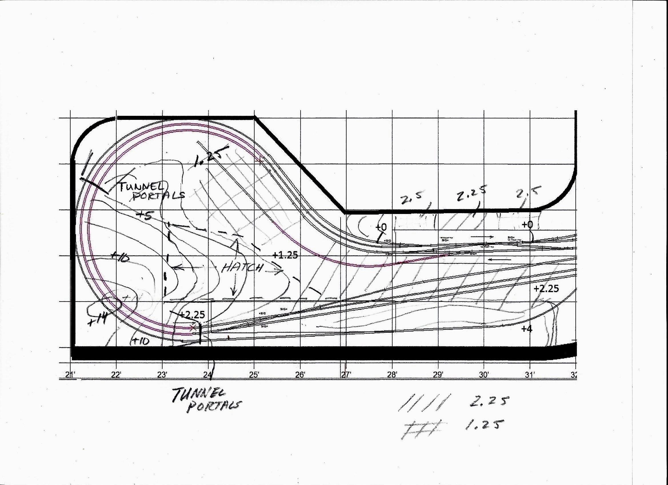 |
Here is my rough topo of the town of Fitzhugh and the mountain at the turnaround end of the Northwest bench sketched onto XCAD printout. The town will be built on a flat plateau at a level of 2.25 inches above bench zero between two mountains. On the South side, it will be bisected by a deep cut at bench elevation +0 for the double track mainlines, which will be spanned by a roadway bridge, and will ascend the grade past the industrial area and around the turnaround curve up to the depot and the other side at elevation 2.25. Most of this curve will be hidden in a tunnel through a large mountain (max elevation +14). the track in the tunnel will be accessed both through a large opening behind the backdrop wall and by way of a removable hatch. On the North side of the town along the backdrop wall, the terrain will rise abruptly up up to elevation +4 the backdrop mountain cuts-outs. |
Tunnel Portals and Portal Retaining Walls
3/7/2019
To begin work on the North bench, I first worked on molding, framing, and installing tunnel portals and portal retaining walls in both mountains at Fitzhugh. I use homasote cutouts to fashion screw-down, slightly oversize, portal frames and then glue plaster cast portals to the frame. The plaster castings are made using latex molds that I made years ago using Chooch resin tunnel portals and walls as masters. Here I will need both double track and single track portals. Before the portal glue was fully set, I ran trains to test clearances. I always like to get the portals adjusted and firmly set before I proceed with work on the mountains.
 |
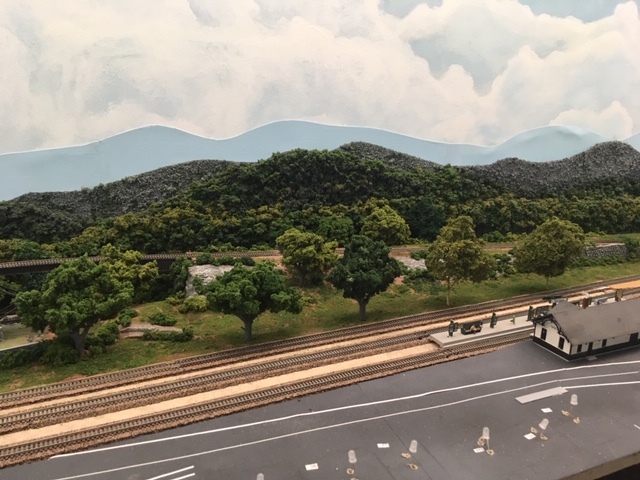
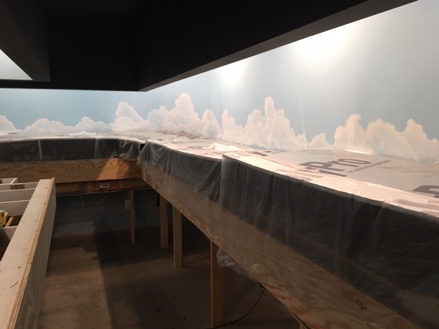
Here is the rough-in of part of the town site and Fitzhugh Mountain. The first step was to set the tunnel portals and portal retaining walls. You can see one of my homasote double track tunnel portal frames installed in the upper left center of this photo. The lift-out hatch base with part of the mountain frame attached to the top is the rhomboid homasote piece in the upper center, and the flat area to the right of that is the industrial section with its siding. The town site is partially visible in the foreground with its deep cut for the mainline. Here I have temporarily set the platform in place so I can do some detailed street and structure planning after the mountains and the lake are complete. |
 |
Here are the portal castings and their latex molds.. |
 |
Two portals and their retaining walls installed,clearance tested by running trains, and adjusted. Because I use a slightly wider track spacing on curves, the double track portals have to be broken in two at the top in order to make a slightly wider opening. The resulting gap at the top is easily patched with Sculptamold, which can be molded and scribed to match the stone work for a totally seamless repair. |
Constructing Fitzhugh Mountain
3/10/2019
I'll begin by adding additional framing to the homasote rough-in. Then I'll install all the exposed rock faces, and tack on the plastic screen; next the Sculptamold, initial painting, ground zip texturing, ground color adjustments and enhancements, and finally ground cover, shrubs and trees.
 |
3/10 Here is the mountain with the additional framing and the rock faces installed.In this photo the hatch is removed to facilitate work on the stationary frame. Next, I'll replace the hatch and reinforce the mountain frame on top of the hatch.Then, I'll be ready for the screen and the Sculptamold. |
 |
3/11 Here it is with the hatch in place and the screen tacked on, ready for Sculptamold. |
 |
3/13 Here is the completed application of the Sculptamold. Now the base coat of paint. |
 |
3/13 Here it is with the base paint coat completed. The rock faces are painted a dark gray, and when dry, they will get several dry brush coats: first a lighter gray, and finally touches of white for highlights. The grassy areas get the red earth under coat, while the forest and brush areas get dark brown earth color. All the earth areas will get "Zip" texturing (powdered plaster of Paris mixed with a blend of colored tempara powders. This will give a highly realistic ground texture, and I'll allow patchs of the earh undercoat to show thorugh in spots. For the exact method, see my post of 3/12/2018.) |
 |
3/14 Here is the texturing complete, the distant forest on top glued in place, and the light gray dry brushiung of the rock faces. Next comes the ground cover and the white dry brush highlights ob the rock faces. |
 |
3/15 Ground cover applied and white dry brush highlights added to rock faces. I'll now install a thin flange to hide the joint running up the meadow - a piece of .015 styrene tacked to one side and painted, textured, and ground covered just like the meadow - maybe a few small shrubs - and it should disappear. Then I'll extend the distant blue mountain cutout on the left and articulate the tree line in front of the patch. Next I'll work on the landscape around the rock faces always with an eye to forcing the prespective - larger bushes around the near rocks - smaller bushes around the rocks higher up the slope will help.The real effective forced perspective will come with the addition of multiscale trees getting samller and perhaos slightly grayer as they get higher up the slope. |
 |
3/18/2019 Here is the mountain with the shrubry added. |
 |
With the trees in place, the forced perspective really works. Here is a view up the same slope. Notice the small trees lining the base of the distant rock face to the left, the even smaller trees that form the tree line at the top of this rock face, and the clump foliage tree line of the very distant forest at the top of the slope to the right. I like to use two types of trees in sizes from 7 to 1/2 inch tall: treesw made by glueing vairious colors of clump foliage to Woodland Scentics "tree armatures," and trees made by gluing coarse ground cover in vatrious colors to Scenic Expresses "Super Trees" material, a dried organic product made from some kind of artic shrubry. I use 3M #77 all purpose spray adhesive, let the bare tree forms get really tacky, and then press clump failage onto the armitures, or roll the Super Trees in coarse turf material in a variety of colors. Then I give each a quick light coat of hair spray and highlight with light green, light gray, or yellow spray paint. |
 |
Completely done. This really worked out well. Now on to the other mountain |
Constructing the Mountain on the Fitzhugh Curve
3/24/2019
I will follow the same path to create the mountain on the Fitzhugh Curve.
 |
Here is my rough topo sketch, with elevations penciled over an XCAD printout. |
 |
Here is my rough sketch of the mountain and the lake. |
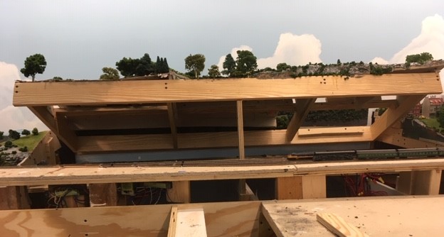
 |
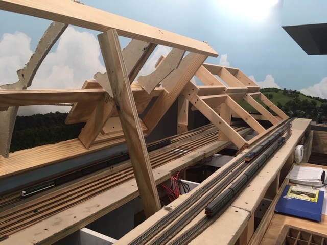
3/24/2019 Here is the fame. I am in the process of adding more cross members to completely support the screen.There is a criscrossing network of track under this mountain, so an ample access opening in the backdrop wall is essential. |
 |
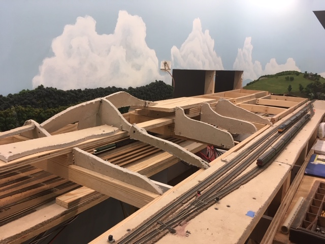
3/25/2019 Here is the completed frame with the rock faces tacked in place. Upon completely this, I again ran trains to check clearances. Things often shift when augmenting the framing. |
 |
3/26/2019 Screen installed. Note the terrace for a distant N scale house. |
 |
3/27/2-19 Sculptamold applied. |
 |
3/28/2019 Base paint coat. |
 |
3-29-2019 Ground cover and tree line completed, |
 |
4-1-2019 Altamont Mountain near completion: rock face dry brushed and landscaped, trees installed, and forced perspective achieved using a Z scale house surrounded by a grove of smaller trees on the prepared terrace about half way up the slope and a gravel drive that disappears in to the distant forest . |
Creating Altamont Lake
4/4/2019
With with the Altamont Mountain complete, I can now tackle the adjacent finger of the lake that will lie at the base of the great smooth rock face. Unlike all the other water features I have built on the A&BR2, which have been, painted, and poured on sheet styrene and then installed, this one will be poured in place owning to the large stone footing that support the traversing steel viaduct. The strategy is to first add the necessary homasote forms to support the screen/homasote slopes down to the shoreline, and then to seal all the way around the lake with Sculptamold and a heavy coat of gloss medium at the seams, then detail paint the shore and the lake bottom, seal again, and finally pour the Magic Water.
 |
4/4/09 Here is the screen and the supporting forms. Notice the long piece of homasote along the track roadbed. This will support a low stone wall, and it abuts the lake below so I can seal the edge. |
 |
4/4/2019 Here are the homasote banks and shoreline that are sealed all the way around the lake. The lake will be between 1/8 and 3/16 of an inch deep, so when the Sculptamold dries, I will seal the shore line up to that level all the way around with a good heavy coat of gross medium and then paint the lake a dark green with lighter green shallows near the shore and my red earth for the shore line. |
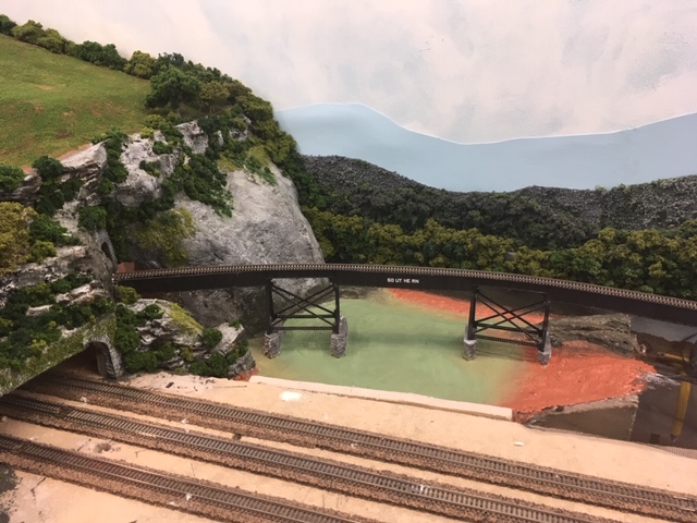 |
4/5/2019 Here is the painted lake bed. When the paint dries, I will seal the edges with gloss medium again, add a few underwater stones and reeds along the shore, and I'll be ready to pour. |
I encountered a serious problem after the pour. As careful as I had been sealing the edges, I missed a spot and about half of my Magic Water leaked out onto the floor before I noticed it and repaired the leak. Repairing a leak like this from the outside of the enclosure can be tough. I used modeling clay to seal along the leaking joint, but I fear that, since the leak was along a homasote seam, that the underside of the homasote will wick up even more of my lake before it drys. The drying time here is about two days, so all I can do is wait and then make a second pour on top of this one to replace the lost fluid. Pouring multiple layers works fine with Magic Water. In fact it is recommended for deeper pours.
4/7/2019 - The first pour is now dry, and it looks good. Although the small rocks on the shore to the left are not fully submerged as planned, the whole thing looks fine, and I will not bother with a second pour to replace the leaked-out Magic Water.
 |
Here is the finished lake. |
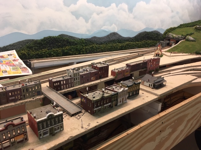
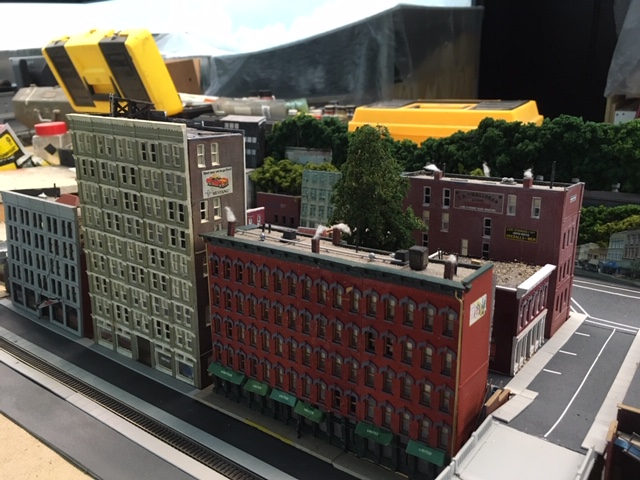
Laying out the Town of Fitzhugh
4/7/2019
While my lake is drying, I can move on the the town of Fitzhugh. As I have mentioned before, I feel it is best to have the bulk of the structures for a town scene complete before laying out the scene so they can be used to fashion the look of the town. Fortunately, I still have a lot of town buildings salvaged from the A&BR1. I spent a little time shuffling them around on the town site trying to get the look I wanted and making plans for handling the walls of the deep track bed cut that divides the town into two parts.
 |
4/7/2019 Once I have achieved the look I want by shuffling the buildings around, I can trace the footprint of each structure onto the homosote, draw the streets and sidewalks and mark the location of any lawns etc. and thus graphically layout the town to scale right on the homasote surface. (Notice I have covered the lake with newspaper to prevent dust from sticking to the tacky surface while the pour is curing.) |
 |
4/8/2019 With the town plan sketched on the homasote, I removed the buildings and cut the .040 styrene street and paving sheets to size, and installed the bridge. |
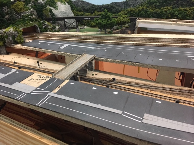 |
4/10/19 The styrene sheet streets and paved areas are next laminated with 220 grit sand paper, spray painted gray with black and white misting, and glued down. Next, the buildings are replaced, re-traced on the road surface, and again removed, Center lines, crosswalks and sidewalks are installed. Center lines are applied using 1/32 inch white graphic art tape. Crosswalks are created using 3/32 inch graphic art tape. I have also pasted down labels for the LED lights. |
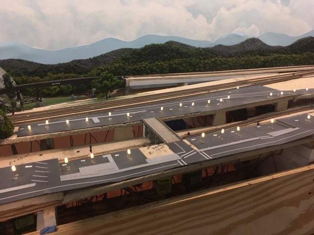 |
4/13/19 LED lights installed power by the switched 12 volt bus. Again using multiple circuits in parallel each composed of 4 5mm bulbs and a 640 ohm resistor in series. |
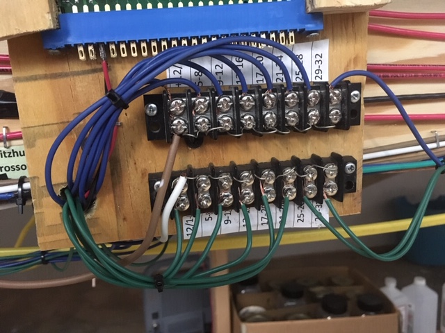 |
4/16/19 Here are the terminal blocks for the Fitzhugh LED lights mounted below a signal control card connector on the wire mounting board. |
 |
4/20/19 Before I go on with the town layout, I'll complete the section of track-side scenery behind the town, between the depot and the backdrop wall, so I do not have to reach over the delicate town to do this work. Here is the Sculptamold painted and ready for ground cover. |
 |
4/22/19 Here is the nearly finished back section. |
 |
4/24/19 Again, working from the back to the front of the bench, I'll complete the church yard section to the right of the newly complete track-side section and slightly behind the town. |
 |
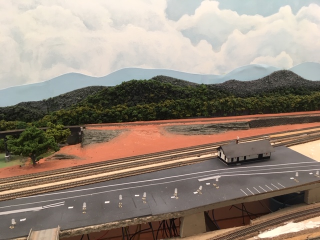
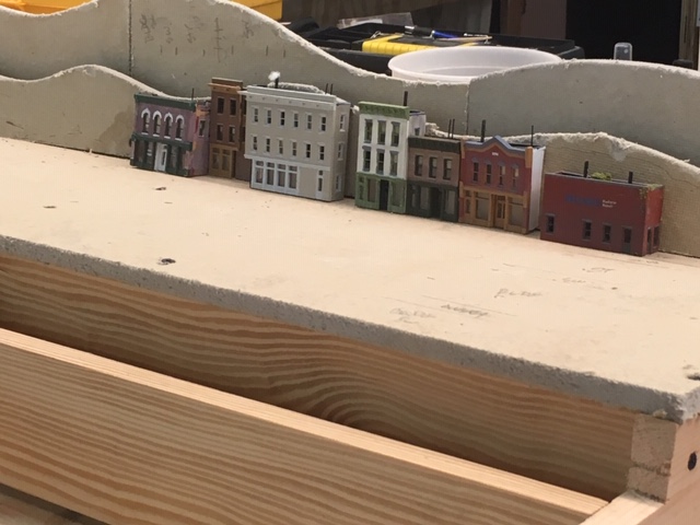
4/29/2019 Finally, the buildings are again replaced, and I am ready to work on the walls of the cut, do some landscaping, plant some trees, and install details like figures, and vehicles and telephone poles etc. Here is the left half of the now nearly completed town of Fitzhugh, |
The Fitzhugh Industrial Area
5/1/2019
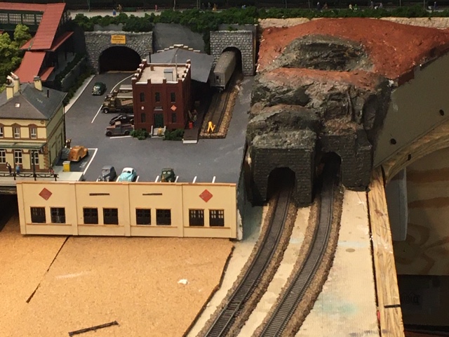
With the both mountains and the town of Fitzhugh and the area next to the backdrop wall finished, the northwest bench is nearing completion. All that remains is the industrial park on the east side of town at the base of Fitzhugh Mountain. The space alloted for this scene is a fairly large and flat and is bounded by the mountain, the town, and the loop of the double track mainline track as it begins its loop into the tunnel under Fitzhugh mountain.
The central industrial feature here will be a gravel company. I have already purchased the Walthers Cornerstone kit for this rather massive structure, and using the diagram on the box, I sketched the footprint of the structure onto the homasote and installed an 1/8 inch cork pad, an Atlas Code 55 #7 turnout, and a siding track parallel to the already installed Fitzhugh industrial spur, again using the specifications on the kit box to inform track layout and spacing. In addition, I have a number of commercial structures salvaged from the old A&BR1 including a fuel oil distributor, a freight house, a stock yard, and a grain elevator. I placed these buildings on the layout and sketched in the footprint of each onto the homasote, and at the same time I sketched in the route of the main highway that will pass through the center of the industrial park and cross the mainline line loop. I also order a crossing gate from New Jersey International.
|
|
Here is the industrial area laid out with structures, an 1/8 inch cork pad for the gravel company, the new siding, and the roadway outline. There will be two small forested hillocks over the open spaces in the homasote, one to either side of the grain elevator. I still have a large open space between the roadway and left hand forest. I'll decide what to place here later after I get a feel for the rest. |
 |
After completing this scene, I added a littel truck farm in the open space - some corn rows, beans, adn atractor plowing rows.Then I ballasted all of the track on the North bench and cleaned the track well and then applied a thin coat of No Ox A Special. Here is the completed section. I have yet to construct the gravel company kit, but the rest is now done. |
Running Trains and Making Adjustments
5-24-2019
While I have been working on the last section of the North Bench, the rest of the layout has spent over a month idle under my dustcover.
 |
Layout with dust cover. |
As I have already mentioned, I don't like to go too long without running trains, so with the completion of the Fitzhugh sexton, I uncovered everything and ran my demonstration schedule routine. This involves six trains running all of the mainline track on the layout complete with full sound, station stops, sunrise and sunset lighting sequences - the works. Things ran quite well, thanks, in large part (I think) to No Ox A Special.
Over the past year or so I have been having trouble with a passenger train that I call the Blue Ridge Crescent. This train is comprised of a Southern Railway Kato E9 unit pulling six Con-Cor silver streamlined cars (baggage, coaches, sleepers, dinning, observation etc.) All of the cars have been retro-fitted with MicroTrains trucks, but they are old, and many have hit the floor more than a few times. Coupler problems and derailments seem unavoidable no matter how much tweaking I do to get things adjusted just right. It has been an ongoing source of aggravation for far too long. So last month, I decided to retire these Con-Cor cars (demoting them to scenery) and replace them with 7 MicroTrains heavyweight passenger units. I spent a considerable amount of time tweaking track and turnouts trying to get these to run smoothly, only to finally find, that 6 of them ran consistently well, while seven caused frequent derailments on curves - just too much weight to keep center cars from jumping the rails.
With this adjustment, I began to get near prefect execution running all schedules my schedules. So I covered everything back up and moved on.
Beginning Work on the West Bench.
6-4-2019
The West bench will be the City of Altamont. It is a raised city terraced into the side of a gentle slope. The city will be built on two hinged sections, which lift up to allow access to the 4 hidden mainline tracks and the 4 hidden sidings below. My plan is to remove the the hinged sections and build the the back half of the City of Altamont on the work bench. The rear sections of these hinged tops next to the back drop are a little difficult to reach in place on the bench, so removing them will make things much easier. After the real halves are completely detailed and wired with lights and everything is glued down, I can simply reinstall these sections by re-attaching the hinges. I can then build and detail the front halves on these hinged sections in place on the bench. I'll start with the northern-most hinged section.
The first order of business will be to install and program the BD4 and the DS64, which will supply block detection of the city's streetcar line, and then run all the the wiring for the North hinged section to a barrier block to be mounted on the fixed bench frame just below the North hinged section. Here I will make connections for the + and - 12 volt switchable lighting buses, and for the streetcar rails - a district 95 B rail common (black) and two A rail power feeders (Streetcar #1 - 95-BD4-76/38-9 and Streetcar #2 - 95-BD4-76/38-11). All of the wiring for this section will come together in a flexible bundled thether and wire into this fixed barrier block. The tether will allow slack for the raising of the section frame to access the track below.
The street car line will consist of two visible and two hidden blocks of track. Two of these blocks, one visible and one hidden, will be part of this North hinged section, and two will be on the middle section of the bench work below. The idea is to use two identical street cars, one to travel down the main street of the North hinged section and then disappear below ground, and the second, which will, after a pause, appear from the hidden section on the central bench below and run to a streetcar platform along side the Altamont Main Terminal Station. Thus, I can have a line from the city to the station without having to have any track cross the over the edge of the hinged section of framework.
 |
West bench with hinged sections open. |
 |
West bench with hinged sections closed. |
 |
North hinged section drawing. The 9.875 inch wide section supported by 2x4s on the right is a raised section 5 inchs above bench. 0. It is already complete, and it carries one mainline track and a siding. The hinges are attached to the back of this section so that the entire rear part of the terraced city will swing up and allow access to the track below from behind the backdrop wall through a large opening in the backdrop wall (far left). |
 |
Block detection for the 4 blocks
of the Streetcar line will be handled by an old BD4 and a DS64 for
loconet reporting. This old BD4, which I have had lying around for
years is a simple devise. It takes A rail track power in
(left), and if it sees voltage caused by a loco running on any of the
four A rail outputs (left), it causes the corresponding trigger output
(right) to go high. These trigger outputs are connected to the inputs
of a DS64 stationary decoder, and the DS64 sends a loconet message
indicating occupancy to the computer via loconet. The BD4 can
present problems with modern loco decoders, but since I
will be running only the two streetcars on the section, this should not
present a problem. As simple as this is, I could not seem to get it to work and I spent almost two days going back and forth with Digitrax because I was not seeing the red light on the unit flicker indicating that message was being sent, only to finally realize that the sending unit in this set up does not give a red light loconet message indication, but all the other loconet devises do. I just was not looking at the other devise, and they had been blinking away all along. Finally, calculating the addresses to use in TrainController in order to process the DS64 occupancy message is not a simple matter, but with a liitle help form the Digitrax online forum, I got it worked out. |
The next move is to detach the Northwest hinged top from its hinges, place it on the work bench and attach the upper level homasote decking to the terraces. Then I'll do some measuring and finalized the town street layout.
 |
Here is the Northwest hinged top on the work bench with the homasote decking screwed down on the upper terrace, Before I go any farther I want to finalize the exact street layout. |
 |
I placed a scrap piece of homosote on
the lower level terrace, and then, using a few assembled structures
as guides, I penciled in the beginning of the street plan,
checking for ample depth for the rows of buildings, for nice wide
streets, alleyways, and sidewalks, and for clearance for the
street car to pass under bridges at the three cross streets. |
 |
Street Layout measurements This differs a good bit for the original plan above. Re-tweaking the plan in the 3 dimensional space before beginning construction almost always leads to changes like this as new possibilities become appearent. |
 |
New street layout overview. |
With these detailed drawings as a guide, I can now layout the silhouettes, streets, and sidewalks for the entire Northwest hinged section. Once that is done. I'll fill in the detail for the rear half of the hinged section working from back to front using the structures I have on hand from the old A&BR1 and carefully noting what additional structures I'll need. This is a big job and it will take some time. As I have done previously, I will post progress photos and text as I go.
 |
6/11/2019 - I began with the homasote mountain silhouettes. The higher one on the very back of the top terrace.will go flush against the wall when the lid is down. The lower silhouette in front is is the near treeline, and is separated from the higher one with a 3/4 inch plywood spacer/nailer in between. This arrangement adds a lot of perceived depth near the backdrop, especially when I use a finer, slightly grayer, foliage cover on the back silhouette and place cutouts of distant buildings and steeples etc. in between the silhouette layers. Next I'll spray paint these homosote forms black, and then begin working of laying out the streets and sidewalks. |
 |
6/12/2019 - Here is the street, alley, and sidewalk styrene cut for the upper level. Notice I have cut no sidewalks for the near side of the street, because most of this will be hidden by buildings. I will not know what is required until all the buildings are in place. |
 |
6/13/2019 - After disassembling and numbering all these styrene pieces, I cut and glued down the 220 grit sandpaper street surfaces and spray painted everything - black undercoat for the mountain silhouettes, a dark gray with black highlights for the streets and a much lighter gray for the sidewalks. I also installed the track for the streetcar line with no cork underlay roadbed, and I glued it all down. Finally, cut a piece of homasote for the factory site 1/2 inch above the upper terrace to perfect the structure fit, and I constructed the two bridge sections I plan to use and placed them on some temporary abutments so I could check spacing and clearances. |
 |
6/14/2019 Having a number of finished structures is helpful when laying
out city blocks Here I have use a few structures to inform the spacing
of the street grid on the lower level. Notice I have also installed a
lighted streetcar platform. Next, I'll install the bridge abutments and
cover all the streets with 220 grit sandpaper, paint tem, glue them
down, and install the bridges and sidewalks. |
 |
6/15/2019 Here is the completed track, street, and
sidewalk
glue down with the platform and the two bridge with abutments and
supports in place.Next I'll install the crossings. I have
yet to
install alleyways, because the width of these will vary depending on
the structures I use in various blocks, so this will come last. |
 |
6/17/2019 Today I am working on retaining walls for the ramps. I am using thin HO scale brick styrene sheets painted a dark red brown and then laminated with .040 styrene backing to simulate finished brownstone walls. Each wall gets a light brown strip styrene "masonry" cap and a concrete footing fashioned from strip styrene. I'll also put the lines and other markings on the streets now as this will be difficult after the buildings are in place. I'll also hook up some track power to the streetcar line, and run the street car back and forth a few time to check clearances and to make sure that the crossings and the sidewalk that hug the tracks do not interfere with the anything running on the track. |
 |
6/18/2019 Finally, I'll glue the foliage to
the mountain
silhouette to the top of the tree line silhouette, and place the
half buildings I have on hand along the silhouette. I have
ordered a dozen or so more DPM structure kits to begin filling in
the
city. While I am waiting for those to arrive, I'll finish covering
the silhouettes with foliage and place all the structures along the far
side walk next to the silhouette and install LED lights in all
installed
structures and then detail the far sidewalk and glue everything down.
When this is all done , I'll reinstall the entire North hinged
section on the layout and finish
detailing this section in place. Here is a short section of the finished back 3 inches of the hinged top. The use of the two homosote silhouettes separated by 3/4 of an inch with photo cutouts in between along with the use of half buildings (about 1 inch deep) gives the illusion of considerable depth achieved in a very narrow band along the back edge of the 3 dimensional scenery. It will also accomplish a nice "invisible" visual transition the to the 2 dimensional mountains and sky on the backdrop wall. |
Finishing Up at Fitzhugh.
6/22/2019
I am away for a few days, and I brought along two structure kits (a Walthers Conerstone depot and a Cornerstone gravel plant) to assemble while I am away. I spray painted all the parts before I left, so all I had to do was assemble these two structures. When I get back I do a little weathering on the gravel plant and the Fitzhugh section will be complete.
Detailing the City of Altamont on the Hinged Bench Top.
6/23/2019
Continuing with rear half of Altamont City hinged top construction, I am in the process of painting, assembling, detailing, and arranging the 10 new DPM structures I just bought. This is slow going because, as I go, I am constructing each structure to fit in a specific place. This means that many walls that are not visible to the viewer can be retained for another use. For example, if the building faces the viewer, the back is not necessary. Likewise, some of the sides are not needed if it abuts other buildings or faces a street perpendicular to the backdrop wall. In this way, I pretty much double the number of structures I can make from the 10 kits.
 |
6/24/2019 /Here are the completed structures for the center block behind the three tall buildings. Because the tall buildings block some of the viewer's view of this area, and because of their orientation on the block, I have omitted many panels here, and save them for use elsewhere. . |
 |
6/25/2019 This all makes sense when the new structures are arranged in place on the city block along with the old structure I already had on hand left over from the A&BR1. Most of the open area in the center of the block is hidden from the viewer, so a few trees, the surface area visible between the buildings, and short sections of the alleyway surface are all that is needed here. There is a lot more detailing to be done, and of course, I need to install lights and glue everything down, but for now, I'll leave this block and move on to the rear portion on the far left (South) side of the North hinged section. |
 |
6/29/2019 The fat left-rear (South) side of the North hinged
section is high ground leading up to the hilltop Cathedral complex that
I have planned for the North side of the adjacent South hinged section.
On this high ground I will place a high-end hotel and a three story
commercial building with shops etc. These structures are built
from European kits and they give a nice contrast to the the
American DMP models in the rest of the city. They will overlook the
courthouse and public buildings (fire house - city hall) complex that
will occupy the left-front portion of the North hinged section
and will be separated from the courthouse complex by a rocky,
wooded, part/hillside. Here is the installed framework and screen for this section. |
 |
Here is the Sculptamold applied, ready for paint, ground texture, and ground cover. |
 |
7/7/2019 Here is the finished rear left area. |
Third Annual Train Room Clean Up.
7/8/2019
In my never ending battle with dust, it is time for my annual complete train room cleaning. This involves getting everything off the center bench and off the floor and off the the shelves behind the backdrop, and then cleaning everything that came off the bench and the shelves and the shelves and bench top themselves, as well as sweeping, vacuuming, and mopping the floor and dusting for cob webs in the lighting soffit and behind the back drop walls. It a job! Ironically the cleaning itself stirs up a lot of duct, so I must be sure all sections of the dust cover are in place before I begin.
7/8/2009 Cleared the entire center bench (5' x 20') right down to the 3/4" plywood temporary decking, swept, vacuumed, and wiped it all down with a damp towel. Took everything out of my roll-around utility cart, cleaned the cart all the stuff that was in it.
7/9/2019 Cleaned out and reorganized all 5 of my my tool boxes (carpentry, electrical, paints, detail, and mechanical) and returned them all to the center bench top.
7/10/2019 Today I removed everything form the behind-the-backdrop shelves, wiped everything off, vacuumed the shelves and drawers, and return everything to its place. I highly recommend clearing out tool boxes and storage areas occasionally, not only to keep the dust down, but also for organizational reasons. Today I found all kinds of stuff that I have been looking for as well as a bunch of stuff I did not know I had. I bought dry wall joint tape just last week, and today I found three rolls of the stuff.
Finished mopping about 3/4 of the train room floor. In the past, I have had the feeling that mopping of the train room floor was more about moving the dirt around than about getting it up. So this time I swept thoroughly and then used my big mop to wet the concrete floor down really well; then I used a damp towel to wipe the water (and the dirt) up. Working in small sections and keeping the towel rung out and clean surely works much better, but it takes some time.
7/11/2019 Floor cleaning complete. To complete the annual clean up, I wiped all the dust covers with a damp towel. I have not run trains in quite a while, so before returning to work on the Northwest hinged cover, I'll remove the dustcover and run some schedules today.
Lighting the City of Altamont on the Hinged Bench Top.
7/12/2019
The last step before replacing the Northwest hinged top back on the layout is to light all the structures I have placed in the back half of the city next to the backdrop wall and to install and wire the crossing gate by the streetcar platform and the the blinking red LED on top of the radio tower. At this point I will create the main wiring tether from the stationary barrier block I placed beside the hinged section on the main bench-frame back in June. The tether will be a flexible bundle of wire long enough to allow for the opening and closing of the hinged section. It will contain the A rail track power for two blocks of the streetcar line (red), the B rail common (black), the 12 volt leads from the DS64s driving the blinking red radio tower LED and the crossing gate LEDs (white/brown) and the switched 12volt lighting power to the lighting distribution block (white/brown).
 |
Here is the LED light distribution block for the hinged section. |
 |
Here is the hinged top on the work bench with the rear section complete. |
Continuing Work on the Northwest Hinged Section.
7/15/2019
I am now ready to reinstall the hinged top on the bench top.
There are four city blocks still to construct and detail. I'll start with the narrow block farthest to the rear. This block will get three tall buildings fronting on the streetcar line. The center building is the tallest of the three and it will get a high radio tower with a blinking LED light driven by a single output of one of my DS64s in the crossing light 800ms blinking mode and a 1k resistor. The tower will be stabilized by four cables made from a .012 inch guitar string. All three tall buildings get interior lights just like the other buildings that I just lit (four 5mm LED in parallel with a 640 ohm resistor). The tall buildings will be secured to the frame using Velcro. All of the the structures on this section must be fastened to the frame so they will remain in place when the lid is angled and open. For the smaller structures I am using double sided tape and Velcro for the larger structures. All details are glued down as I continue work of the other city blocks nearer to the front edge of the bench.
Also, I completed the wire tether and connected everything to the barrier block I installed earlier on the stationary part of the bench. All LED lights, the crossing gate, tower blinker and the streetcar line track power are all functioning along with the sounds of crossing bells and and the streetcar clapper bell.
 |
Hinged top reinstalled on the stationary bench and the nearly completed layout of the remaining town buildings |
 |
Hinged top open. Track beneath is accessed from behind the backdrop wall. |
The Courthouse, Fire Station, and Police Station.
8/24/2019
I have been on vacation, and I am now back. This week I worked on the last little section of the hinged top, including the addition of two municipal buildings for the City of Altamont.
Planning the Southwest Hinged Top
8/25/2019
I now have only to plan and install the north hinged bench top scenery, and I will have completed the entire layout perimeter. Before I begin with this last section, in order to ensure a good transition, I want also to plan the adjoining section of the center bench top, which will contain my grand passenger terminal. I will begin with a number of rough sketches, and then I'll install the 3/4" plywood decking and the homasote top for the first 8 feet of the center bench. That will allow me to mock up my terminal buildings and platforms in two dimensions of the flat top before constructing the terracing. As I did everywhere on the layout, I'll later install all turnouts on long prefabricated plywood/homasote runners so I can do the underside wiring on the bench and thus avoid having to crawl around under the bench - I am getting too old for that. I will construct these runners now as part of the bench top construction
Next, I'll construct two removable sections for the back half of the hinged top. Since this hinged section hinges at the backdrop wall, the topography near the wall must be removed to allow clearance when opening the section, and since the back-right-hand area is the only place on the layout that I cannot easily reach, I have to make the two back sections removable. This is not the most convenient arrangement, but it is unavoidable, and it will not create much of a problem since the rear sections contain no track, and the only wiring on them will be for structure lights, which will be on plug so I can remove the section before opening the hinge.
 |
Rough sketch for the scenery on the second hinged top. |
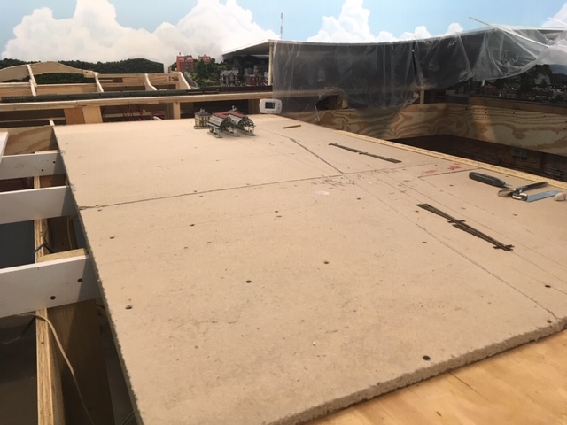 |
Decking for the first eight feet of the center bench. |
 |
Decking with the prefab track/turnout runners removed. |
 |
Rough sketches and preliminary plans and elevations for the terminal complex and the terminal complex mock up. As always, it really helps to have most of the key structures already fabricated so I can get the layout, track spacing and all the clearances just right. Here I have just roughed things in with pencil lines on the homasote. I'll develop better drawings and then get it dead accurate after I install the cork. Only then will I install the track. |
Constructing Scenery on the Southwest Hinged Top.
9/2/2019
First, I'll use homasote to make topographical framing for the two removable back sections. Then I'll place the removable sections on the bench and install the homasote terracing, roadways and any additional topographical framing. Then, I'll add the plastic screen, rock faces, and finally the Sculptamold and paint. At this point, I'll do some detailed structure selection and placement planning and finally I'll add the ground texture, ground cover, landscaping, trees. lights, and other details.
 |
Right-hand removable section completed on the bench. |
 |
Removable sections in place and road runners, framework and terracing complete. |
 |
Left-hand removable section frame in progress on the bench |
 |
Both removable sections complete on the bench. |
 |
Both removable sections in place on the hinged top. I now have only to wire up the lights for these sections. Since they will be removable, I'll have to devise some kind of easily accessible, detachable plug for each section. |
 |
Completed left hinged section with removable section in place. |
This hinged section looks good, and it works - that is to say, when open, it allows good access to the track and turnouts of the main line track and the hidden yard below. However, it has some problems. The removable sections are very awkward to handle, and the small one fits too tightly against the backdrop, which causes foliage to be scraped off and settle on the track below every time it is removed or replaced. I think if I cut these lengthwise so they are about 4 or 5 inches from the wall, I will be able to open the entire hinged section enough to service track below without removing the removable sections. The elevations are such that the gap will be hidden from the viewer, and the void will actually help with the illusion of depth between the high ground on the back of the removable sections and the flat mountain cutouts attached to the backdrop wall. Also, now I don't have to fumble with the light plugs, I can just make a flexible tether like I did on the other hinged section,.
 |
Completed left-hand hinged section after alteration. |
 |
Left-hand hinged top open after alteration. |
Installing Lighting Baffles Above the Center Bench
10/2/2019
Before I begin with the scenery on the center bench, I need to install some lighting baffles overhead. The lighting soffits I have designed do a good job hiding all the lights. They hide both the fluorescents and the HUE lights as well. There is, however, one place in the room that is a problem in this regard. If one stands at the East end of the center bench and looks Westward back down the center section toward the City of Altamont, the lights overhead are visible. The solution is to hang several opaque baffles running laterally across the soffit above the center bench and hanging down about a foot or so from the ceiling. I will have to experiment a little with the size and with the material (fabric or foam poster board). Needless to say, once the center bench is covered with scenery, this overhead area will be much more difficult to access. So I had best do this now.
 |
The deep lighting sofit hides the lights well, except when looking westward back down the center bench. |
 |
Three baffles installed. I painted some wooden strips with hooks sky blue and glued them to the ceiling. Then I used florist wire to hang sky blue, 12" x 36" baffles made from foam-centered posted board. This works, but I think sky blue pleated fabric that is the full width of the sofiit might look better. I've ordered 1 light blue polyester skirt -12" by 48" . |
 |
Uugh! Bad idea! I think the poster board is a much better look. Perhaps I can find some that is the full width of the soffit. |
Constructing the Grand, Terraced Altamont Terminal Complex.
10/7/2019
Now it is time to pull out the plans and sketches I made back in late August and proceed with the construction of my grand terminal complex. This is a complicated affair, with multiple levels connected by covered stairways (3 x Faller #20119). The complex will include two north-south platforms on the upper level, and four east-west platforms for the seven tracks of the ladder and the streetcar track down at bench-level below. These eight tracks will all terminate under the main terminal structure, so I'll need to build the entire structure on a hinged terrace so I can service the track below.
 |
10/7/2019 First I installed the 1/8 inch
sheet cork roadbed for the eight tracks of the lower level ladder, and then I
drew the track center lines and the platform locations on the cork. Next I laid out the hinged terrace. Here is the basic terracing layout with a few
key structures in place to check alignment, spacing, and clearances. The
underground overhead clearance is 1 11/16 inches, easily high enough for my tallest passenger car. |
 |
10/8/2019 After
a final check of the track spacing, I drilled the dropper
holes, and laid and glued down the track. |
 |
10/10/2019 Before I continue working on the hinged terrace, I will install the mainline track entrances to the center bench. This will eventually be a loop all the way around the center bench with entrances from both the North and the South bench at either end. Both mainline entrance tracks come in from the hidden yard under the city, entering just to the south of the terminal complex. It would have been easier if I had installed these runners,roadbeds and tracks before I built the hinged sections on the West bench, but I managed to install both curved sections, including 3/4 plywood runners, homasote surfaces. cork roadbed, and track. The more scenery I build in the area, the harder it will be to install these mainline runners and track, so it was best to do it now while things ares still open. |
 |
10/11/2019 I next installed the hinged terrace, which will support the main terminal building, the two freight houses, and another double, covered stairway (2 x Faller 20119), which will supply pedestrian access from the terminal building to the the upper level platforms. I also installed the terrace supports. Here is photo of the hinged terrace open. Notice I have used sized lumber and cork to construct the supports.. This is a practice that I employ throughout the project to achieve my desired elevations. Lumber sizing is very accuarte, and this method is much easier than cutting pieces to size. In this case I achied exactly a 1 5/8 inch overhead clearance by using a 1 x 2 ( which I know to be exactly 1 1/2 inches and a 1/8 onch strip fof cork. |
 |
10/12/2019 Here I have installed the track and two turnouts for the mainline entrances while continuing work on the layout of the depot complex on the hinged terrace. |
 |
10/18/2019 Over the last few days I have installed tunnel portals, retaining walls, paving,
street markings and sidewalks.
as wells as LED light wiring for all the sheds, platforms,
and stairways. I'll be using directional 3 mm LEDs in series groups of
four wired in parallel each with a 680 ohm resistor and for the main
terminal building and the two freight houses using 5mm LEDs in
series groups of four with a 680 ohm resistor. To the left is a photo of the completed
light wiring with terminal block (yet to be labeled) and hinge-tether
for the hinged section. 10/22/2019 Wired the streetcar tracks and programmed the streetcar sequence that simulates a shuttle between the main streetcar platform in Altamont City to the streetcar platform of the terminal complex below using two identical streetcars (see post of 6/4/2019). |
 |
10/29/2019 Next, I built and installed installed
the upper stairways and the two freight houses
and and some additional covered and uncovered platforms, and
two dummy spurs beside the freight houses. Finally,
I finished things off with landscaping, vehicles, figures, and other
details to
complete the scene. Here is the finished hinged terminal terrace. I
have yet to complete the platforms for the crossing tracks above the
terrace. |
Platforms for the Altamont Terminal Upper Level crossing Tracks
11-5-2019
Now, I will construct two long platforms for the upper level of the terminal complex. Each will be made using 6 sections of Walthers butterfly platforms with four 3mm LED lights in each section. The light installation will be accomplished using the same method described in the entry of 9-23-2016.
Bringing a Second Computer On line and Installing NET Software
11-8-1019
As I mention much earlier in this blog, since I plan to have a separate 4D Sound system for the center bench, I'll need two computers to run the completed A&BR2. I'll use the first computer (A&BR2-MAIN) to control and supply 7.1 surround sound to the the peripheral part of the layout next to the walls, and I'll use the the second computer (A&BR2-TERMINAL) to run and supply stereo sound on a separate sound system to the center bench section. The two computers will be networked together using a TCP/IP network and running Railroad and Company's "Net" software. Both computers are up and running, and I have installed TC and 4D Sound on both as well as the drivers for my current surround sound box and for the lighting servo controller, and I am running schedules complete with sound including all train sounds and a number of stationary sounds as well, I am also running all lighting effects including HUE light sunrises and sunsets.
Before I buy and install the Railroad & Co. NET software and a second sound box and speakers, there are a number of things I need to do to insure that both computers are setup to handle NET.
1. First, I need to setup a TCP/IP network. This should be simple enough, but there is a problem. The second computer has been sitting idle for well over a year now, and in the interim, Microsoft has issued a major update, which, among other things, completely changes the way Windows handles home networks. So, the first thing to need do is to complete all the windows updates needed to get both units running the exact some version of windows with all the same updates completed on both. Then I'll network them together using the new Windows networking procedures. This will entail making the Internet connection on both computers private and then setting up file sharing. Whether or not this setup constitutes an adequate TCP/IP network environment for RR&Co's NET software, I do not know. Whatever the case, I also plan to experiment with a hard-wired, Ethernet network network as well.
2. The next move is to install a second Computer/LocoNet interface for the second computer using a second RRCirkits unit attached to and installed in the second computer, A&BR2-TERMINAL. I'll also purchase and install a second ENCORE sound box on A&BR2TERMINAL and speakers for the center bench. I'll then test these interfaces by disconnecting the A&BR2-MAIN interface from loconet and running TrainController on A&BR2-TERMINAL using the current .yrrg file to control all of my current layout. This will also test the HUE lights wifi control interface, the servo control for the fluorescent lights, and the new surround sound interface with 4D sound.
3. I'll then create new .yrrg files for both units, removing all the blocks on the center bench (except the two entrance/distributed blocks from the file running on MAIN, and using only the blocks on the center bench on TERMINAL. Then I'll test each computer/datafile setup separately. (I have laid and wired up only the two dsitrubuted blocks on the center bench, but this should be enough for the initial testing.)
Once all of this done, I can purchase and install the NET software and run both computers at once - with MAIN controlling and supplying sound for the peripheral layout, and TERMINAL controlling and supplying sound for the center bench. The two blocks that I have laid and wired up on the center bench are the entrances to this center section from the peripheral section. These will be the only "distributed blocks," and thus they will be included in both new .yrrg files. Once all of this is accomplished, I will be ready to experiment with some inter-sectional schedules that will pass control from one computer to the other.
11-12-2019 I have orderered a second ENCORE Sound Box and four more Gear Head desktop speakers. I have encountered a problem with computer to layout interface on the second computer. One of my RR-Cirkits Locobuffers works fine for this interface, the other works after a fashion but exhibits some anomalies. After a discussion with the designer at RR-CirKits, I have ordered a new one.
11-13-2019 I received the speakers today, and, after testing them using the left/right and center outputs of my existing sound box, I began work on their installation on the center bench.
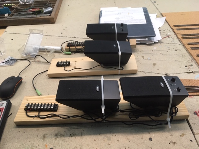 |
Mounting boards for the center speakers for the center bench in the foreground, and for the left and right speakers behind. Barrier blocks include a 5 volt power pair, 2 pairs of sound box-to-amplifier wires along with separate ground wires to prevent hum, and, in the case of the left /right speakers, a long pair connecting the amp in the right speaker to the left speaker. Unlike the peripheral speakers fed by the surround sound 7.1, I want these stereo speakers to be non-directional, so I will mount them all centered on the underside of the bench facing down toward the floor. |
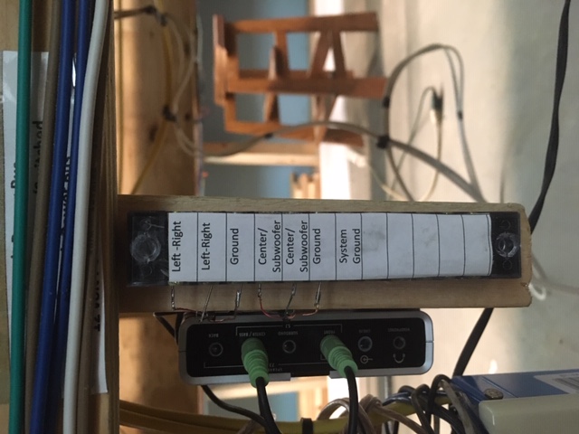 |
Here is the installed 7.1 surround sound box and it's associated barrier block. I want a stereo output, but I'll set this up in 7.1 surround with the subwoofer turned off and nothing pliuged into the speaker ports for L/R rear or L/R surround. This way I'll get stereo with a descreet output to the center speaker. |
11-18-2019 I have encounter a small problem. Here is my post to solicit help on the Train Controller forum:
Greetings.
I am about to add a large, new section to my N scale Altamont and Blue Ridge Railway, and I plan to use a second computer to exercise control over and to supply 4D sound to this new section with the help of TrainController Net software, which I am am about to purchase.
I have two identical computers running Windows 10, They share files and a printer using a conventional WIFI LAN network with “Network Discovery” on. Both computers are running the same version of windows 10 and both are running the up-to-date version of TrainController Gold (one with the license stick installed, and one running in the demo mode). They are both connected to the layout using separate RRCirKIts LocoBuffer units (Computer #1 is connected to LB-Unit A, which always installs on com5, and computer #2 is connected to LB-UnitB, which always installs on com4.
This all works fine when I start up in the morning, but there is a problem. If I close TrainController on computer #2. When I restart TC, it cannot find the LocoBuffer, while computer #1 works fine after a restart. I tried a new LocoBuffer unit with computer #2, and it does the same thing, so it does not appear to be a problem with the LocoBuffer unit. In troubleshooting, I find that if I disconnect LB-UnitB from Computer #2 while TC is still running, and l then plug in LB-UnitA, and then reset the TC connection to com5 - it works. What is odd, is this: with TC still running, if I switch computer #2 back to LB-UnitB and reset the TC connection back to com4, - it works. When I exit the software and restart TC– it fails.
Furthermore, if I swap out the Locbuffers, so Computer1 is connected to LB-UnitB and Computer 2 is connected to LB_ UnitA, the problems follows LB-Unit2/com4, but it is not the LB Unit, for if I install a new one it too, fails.
The next morning, everything boots up fine, but com 4 fails on a restart.
This appears to me to be some kind of com port conflict, that under some (but not all) conditions effects com port 4 on both/either computer(s), but I can’t be sure. I tried forcing a LB-UnitB from com4 to com6, but it exhibited the same behavior.
Any ideas?
_________________
Pete Caldwell
Altamont and Blue Ridge Rwy (N)
Digitrax DCS100/PM42/DT400/BDL168/DS64/SE8C
LocoBuffer/ TC Gold 9.0B1/Windows 10
11-19-2019 I purchased NET today and after installation the com port problem went away. Here is another TC forum post:
Greetings
I got my NET license today and installed NET on both computers and got things working pretty well, and the problem went away. This is good, but a little frustrating because it does not explain what the problem was.- something with the ports and the windows network that went away when the two computers running TC were properly networked together using NET.
I did have a few issues while I was setting things up. A couple of times TC went into the Freeze mode and computer #2 lost its connection and could not find the LocoBuffer on com4 - even though it showed it was still connected to com4. But now with NET running all I have to do is re-connect to com4 using the Digital Systems window on the Railroad Menu.
Now that I have everything all set up, things appear pretty stable. We'll see.
I'll now move on to getting NET fully set up and tested and tweaking the sound and creating shared blocks and remote test schedules that allow me to pass schedule successions from one computer to the other.
| Here are the two computers running NET. |
11-20-2019 I set up my distributed blocks at the entrances/exits to the new center section, and they seemed to work fine. Next I tested the sound on computer #2. It did not work. After some troubleshooting, I decided to reinstall the 4D sound license, and that fixed the problem. ( I am not sure I ever installed it in the first place.)
While I was troubleshooting the sound, I realized that computer #2 was operating in the demo mode despite an apparently successful sign in. After messing with the windows network setup, I finally realized that the license it needed was on the RR &Co USB doggle on computer #1. I was sharing the C:\\ drive but not the doggle, which showed up as E:\\. This little drive also had to be set up for sharing. Once this was done, the sign-in worked fine, and computer #2 operated in the licensed mode. Unfortunately, while I was fiddling with the windows network, I changed something, and now the distributed blocks I set up do not work, I spent the rest of the day trying to set this right.
11-21-2-19 With a fresh mind I got to the bottom of my problems pretty quickly. I checked to make sure everything on the c:\\ drive was shared by everyone on the network with read&write&full control permissions. I checked that password sharing was off in all cases (it was not), and I checked that network discovery was allowed on both computers. This fixed it. I had inadvertently made a change or two.
Then I set up my schedule hand off by creating a couple of remote schedules that pass a schedule successor from one computer to the other when a train arrives in one of the two distributed entrance blocks. This all works great. I do sometimes have a bit of a time getting both computers connected at start up owing to the squirrelly com port problem on computer #2. But everything does eventually connect, and other than this little anoyance, it all works great so far.
Now, I will do some sound tests.
11-22-2019 Sound works fine. When train is in the distributed block, I get sound from both systems. I could the sound off on one , but I think it is best with both. This is not perfect, but it is not much of a problem.
Hillside Transitions from West Bench to Center Bench
11-23-2019
I began this transition when I built the terracing for Altamont Terminal, now I'll complete it by adding a rocky slope with two tunnel portals for the entrance mainline tracks to North of the terminal. Before I begin. I'll hook up the lights in the upper level platforms at Altamont terminal and completely clear the center bench in preparation for track laying, re-organizing the roll-around cart and placing the tools I use regularly on it, constructing some shelves behind the back drop wall for my tool boxes, and moving the computers and monitors to a temporary table.
 |
Upper level platform lights |
 |
Roll-around cart re-organized. |
 |
New toolbox shelves behind the back drop wall. |
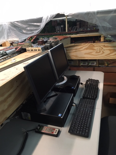 |
Computers on the temporary table. |
 |
Portals, rocks, and framing for the North transition base paint coat. Note the top is removable so I can access the track in the tunnel. |
| North transition complete. | |
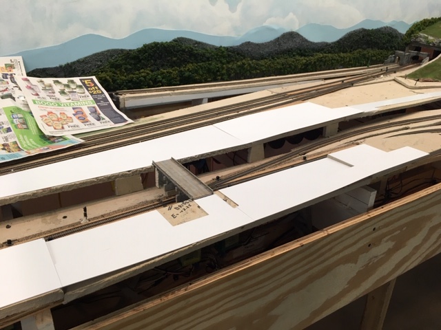
| Center bench cleared, |
Constructing the Altamont Terminal Ladder
12-5-2019
Today I'll begin work on the terminal ladder, which will include seven #7 Atlas Code 55 turnouts. As before I'll wire the turnouts, Tortoise machines, dwarf lights, and barrier blocks on prefab runners, so I can easily have access to the under side without having to crawl around under the bench. Laying this out will be a little tricky, because I want the turnout spacing to reflect the two by two sapcing dictated by the platforms, and there is an under-the-bench support member to work around. I'll have to take care that the layout of these turnouts ovewr this support avoids any interference with the Tortoise machines. I can notch these supports to accommodate track and lighting wiring, but the turnouts must be placed in such a way that the Tortoise machines are clear of these supports. Also, before I install the turnouts, I had best finish installing the lighting baffles in the soffit above while I can still climb around on the cleared bench.
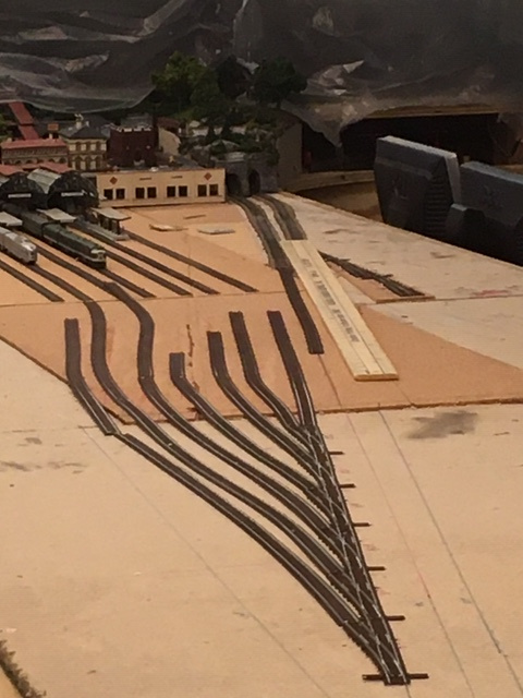 |
Here is the initial layout of the terminal ladder with the turnouts connected one to another and the rest of the track roughly tacked in place.Once I am satisfied with all of the alignment, I'll take the track up, glue down the cork, cut the runner, redraw all the track center lines on the cork, and install the turnouts. barrier blocks, Tortoise machines, and lights. Once this completed and runner is back in place on the bench top, I'll lay the rest of the track and glue it down. |
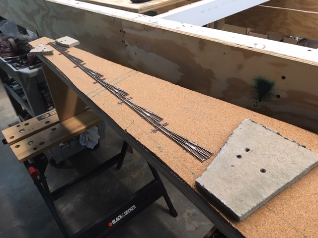 |
Here is the cut out section on a special bench with the cork glued down and the track center lines drawn. It is now ready for the laying and wiring of the turnouts and the installation of the Tortoise interfaces (see page one of this blog - entries for 6-7-2016 thru 7-8-2016). I'll now paint and weather the turnouts, and then wire and install them, along with the barrier blocks, Tortoise machines, and dwarf signals. The temporary homasote pads are designed to ride on the supports and protect the turnouts and lights when I flip this over to work on the other side (bottom). |
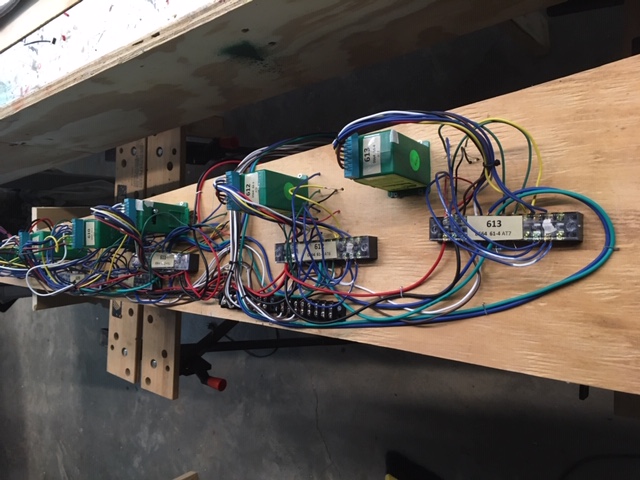 |
Intallation complete (underside). |
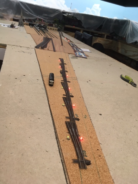 |
Installed ladder module. |
Installing the Rest of the Mainline Turnouts on the Center Bench
1/6/2020
I am back from my Christmas holiday and ready to continue work on the center bench. Completing the main line track on the center bench will involve constructing and installing the two more prefab turnout modules (#602 and 603; #604, 605, 606, and 607), and running the 98 Undetected Routes and Turnouts Track Power A and the 98 Com Track Power B buses on the wire mounting board and then running feeders out to these modules. Once this is complete, I can cut bus wires and and feeders and install all the rest of the 96 and 98 mainline detected track blocks. N scale track laying requires great perscisoion and should not be rushed. This will take some time.
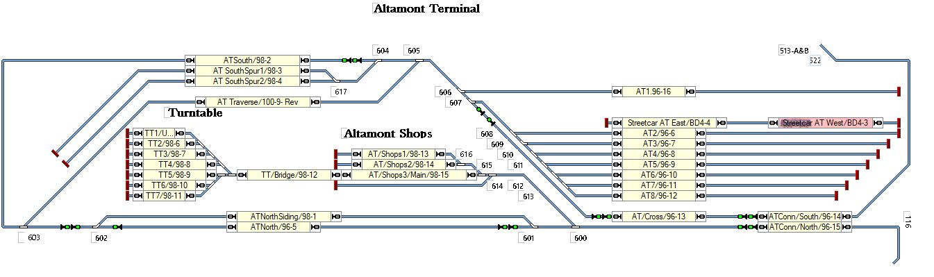 |
Center Bench Track Plan |
2/6/2020 Today I completed track laying and wiring for the Altamont Terminal lead and ladder and all of the main line track on center bench including the loop and the auto reversing traverse track, which allows locos and trains to turn around. I'll install and wire track for the rest of the sidings, the shop complex, and the turntable round house complex after I work out the elevations and rough in the terracing, the ramps, and the surrounding topography.
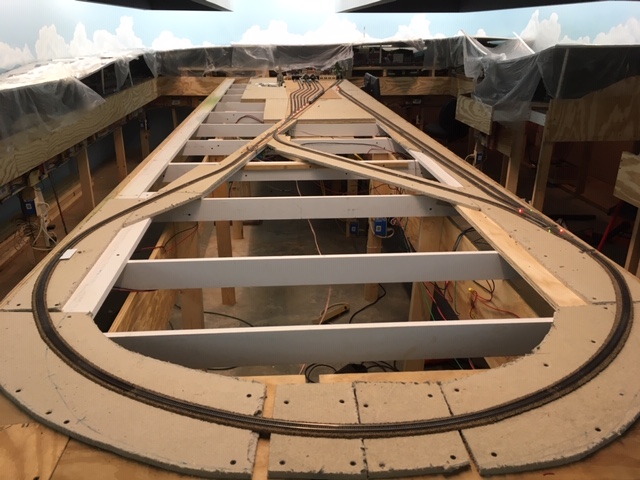 |
Track laying and wiring complete for all the center bench mainline track including the loop and the auto-reversing traverse track as well as the Altamont Terminal lead and ladder. |