Go to
A&BR2
Home Page
email Pete at:
altamont@altamontandblueridge.com
I began this blog as a way of collecting and organizing my thoughts
regarding my proposed new layout, The Altamont and Blue Ridge2, and I
plan to continue blogging into the construction phase on the project.
Along the way, I will broach almost every aspect of state-of-the-art
model railroad design, construction, and control.
Should you have questions or
comments, you can email me at the following address:
altamont@altamontandblueridge.com
From the the feedback
I have received, I can see that many are finding my blog entires as
they search the Internet for information on various model railroad
topics. To aid these searchers as this blog gets longer and longer, I
am including a Table of Contents and an Index
that can be seen by clicking the following links:
JULY 2015
To
Be or Not to Be?
7/14/2015
If you have explored much of this website, you will probably
have noticed that the A&BR is pretty much finished. Of course,
these things are never really finished; still, all the track is
laid; the bench-work is completely covered with highly detailed
scenery; all the lights, signals, and other refinements that I
originally planned are in place and operational; and all of the the DCC
control and sound hardware
is humming along nicely with all of its software programed
and tweaked. For the last year or
so, I have busied myself with simply keeping things
running smoothly. Now, operating a model
railroad
may have its pleasures, but it is the planning
and building of these things that really excites me.
Lately, I
have been feeling the need to move on. I
find
myself dreaming of a bigger and better train room. As
it happens, I am currently considering adding an addition to my
home in the North Georgia mountains. There will be a large (approx 40'
x
20') upstairs space to accommodate two bedrooms and a bath. Should I
instead use this space for a new train room? Should
I take on such an enormous project at my age?
This is all conjecture at this point.
Nonetheless, whether I build it or not, I find myself planning a
new layout. This is a complex matter, and so I begin this blog as a way
of organizing and documenting my thoughts. At the same time, it
quickly becomes a tutorial detailing the kind of thinking that goes
into planning and organizing this kind of project. If I continue to the
actual building stage, this blog will also function as a detailed "how
I build it" tutorial. But for now, it's just away of talking to
myself.
I begin the planning process by asking myself lots of questions about
the proposed layout. Perhaps the most intriguing of these
questions is: "What
would I
change
about my current layout if had the whole thing to do over?"

|
Begun
in 2008,
the current N Scale
Altamont and
Blue Ridge
Railway occupies one bay of a remodeled two car garage. The
train room is 21' x 12', with custom electrical, lighting, and HVAC
systems. The DDC layout is controlled by Freiwald "TrainController"
Software with train-tracking 4D Surround Sound. Current programed
sequences
operate ten trains at once in a complex 15 minute demonstration "train
show".
Do I
dare tear this whole thing up and
start over? |
What Would I Do
Differently?
7/15/2015
I have been thinking about these questions for several months
now - just kind of day dreaming, and playing little "what if" games. A
few weeks ago, I decided to make a list of the the things I would do
differently were I to do it all again. Now, mind you, I am generally
quite happy with the current A&BR. I mean, there is a lot that is
right with it, and at first blush, there didn't seem to be much wrong
with it. To my surprise my little "do-over" list turned out to be
quite long, and the more I think about, the longer it gets. This seems
to me compelling. Perhaps I really should start over.
There
are a number of areas of focus in the "do-over" list:
1.
Room Lighting. Currently I have dimable daylight fluorescent
fixtures with UV bulb filters, all hidden from view in a sofit
above the
bench-work.I am delighted with this set up. The lighting
is warm and bright, and it looks great, but there are a few
flaws.
As you can see in the drawing below, outside
of the lighting sofit I have conventional
track lighting - two dimable circuits. I originally planned to use
these
for a kind of hot-side/cool-side colored light to add depth and create
twilight etc., but
although the incandescent track light cans when angled toward the
layout cast nice realistic
shadows on the ground, they also cast shadows on the backdrop which
is not a desirable effect. If I had it to do over, I would
mount these lighting tracks inside the sofit where I could angle them
only slightly and point them away from the backdrop. It is also
possible that I really don't need these track lights
at
all.
 |
On the current A&BR I have track
lights outside the sofit angled toward the layout. If I had it to do
over I would raise these and mount them directly on the ceiling inside
the sofit. Or perhaps omit them all together. The warm fluorescents
look
great and give plenty of light. |
Another
problem is that the
fluorescent dimmers I use are
not computer controllable. So I computer automate room lighting
mechanically,
moving the dimmer sliders up and down using servo motors controlled by
a program I wrote for an Arduino microprocessor which executes dimming
sequences triggered by inputs from stationary
decoders. It's a little bit of a Rube Goldburg, but it works fine.
Still, in an ideal world computer addressable fluorescent dimmers would
be very cool.
 |
Receiving input
from stationary decoders, Arduino controlled servos mechanically move
room light dimmer sliders on the current A&BR. A bit of a
Rube Goldburg ... but it works fine. |
Most likely, I'll control room lighting servos
with dimming programs
that I will write in C#. These little program will send string
serial commands over a USB to a servo controller board like my SSC-32.
The individual programs can be called from
Traincontroller using automatically triggered push buttons using the
"Execute" option in the each pushbutton's operations window. This way I
will be able to address and operate multiple servos
simultaneously. I have also developed a better way to mechanically move
the dimmer faders with servos using small tension rods with clevises on
the ends. More on this later.
Lastly, I would add individually switchable, built-in, work lights
under the bench and in all behind-the-layout access aisles.
2. AC.
I am pretty happy with my current AC wiring setup in general, but if
had it to do over, I
would add more outlets and a master outlet on/off switch.
3.Control
Desk. When I built the current A&BR I did not design in a
control desk. This was a mistake. In any future setup, I would design a
dedicated control area, with built-in desk for the computer key board,
built-in computer monitors, loconet
access, etc.; and I would also move all short circuit indicator
lights from the PM42s to a built-in panel in the control area.
4.
HVAC. I would have a special particle-removing dust filter system like
the
ones used in hospitals
etc. built into the HVAC air handler.
5. Separate Undetected Power Bus for Turnouts. I would employ
a dedicated turnout track power bus. According to most TrainController
Software users and TrainController creator Jurgen Freiwald, it is
best in most cases not to
have turnouts as part of detection blocks. Rather, they should
receive power directly from their own power bus and be designated
in the
control
software as part of undetected
routes between blocks. On the current A&BR1, I incorporated a
number
of turnouts into my blocks. It's not really a problem, but it would be
more elegant had I used a turnout bus and made them all routes. The
fact is, I could have done a better job laying out the block scheme in
general.
6. All of this aside, perhaps the single
most glaring issue with the current A&BR is
access - both to wiring and in some cases to track work.
Although
quite functional, the
wiring of the current A&BR is really pretty messy and hard to
service.
At age 70, I am not quite so inclined to go crawling around under
the bench with a soldering iron as I once was, and I have a few tunnels
and a
hidden
yard in which I would probably be unable to address any serious track
laying issue owing to lack of adequate access.
 |
Wiring underneath the
current A&BR works great, and I have experienced very few problems,
but it is pretty chaotic looking,
poorly labeled, and difficult to service. |
To address the track access issues, I am envisioning a space large
enough to accommodate a sort of room within a room, which would
feature a narrow access isle around three sides of the layout
behind
the backdrop, thus allowing open, behind-the backdrop access to all
tunnels,
especially those in
the corners of the room.
To
address neater more accessible wiring, I envision a system
of recessed cable troughs running just below the fascia board of
the
bench-work to carry all bus wiring including 12 agw track-power
buses, 12 volt layout lighting buses, as well as
stationary decoder feeds and signal feeds. On the front of this
trough, mounted
horizontally for easy access, I propose a long narrow mounting board
for stationary decoders,
signal cards, other control cards, and the loconet cable. All 16
agw
track feeders and 18 agw light
feeders would connect to the
power buses in the troughs and go out in parallel runs, front to back,
through the back wall of
the trough, underneath the bench-top to the appropriate track or
light droppers. Decoder and
signal
outputs would likewise run in the trough and feed out to turnouts front
to back parallel to secondary feeders. Loconet cable would run along
the bottom of the mounting panel below the power cable trough
to minimize crosstalk. (Note: I have ditched the idea of the troughs in
lieu of different approach - see the post dated 11/30/2015)
 Access
Isle Access
Isle
|
New cable trough design.
Trough will
attach to
bench legs and run below and slightly behind the fascia board of
the bench. It will be hidden by a black table skirt that attaches
to the lower edge of the fascia board and goes all the way to the
floor. |
7.
Structure Lighting. On the
current A&BR, I used Christmas tree lights to
light structures (gangs of 6 in series
with the gangs wired in parallel all running off 15 volt, 5 amp
buses). On the new layout, I would change to 5mm
LEDs run from a single 5 volt bus. They are smaller and much
easier to correctly position inside a
structure, and they lend themselves to a much cleaner and more
precise installation
all
around.
8.
Tortoise Interface. On the
new layout, I also envision a new design for
a tortoise switch machine interface that is clean and easy to install -
just an eight position terminal block and a pigtail with a female edge
connector leading to the tortoise. This is similar to what I now
have, but I soldered directly to the tortoise and did not use the
female edge connector which would have made things much neater. Also,
the way I handled droppers everywhere on the current
layout (and especially on the turnouts) is inherently messy. There
is a better way, and I will not make
this mistakes again. (Note: see post of 12/3/2015)
9.
Individual On/Off Block Power Switches. Sometimes a short can be hard
to find. On the A&BR2 I will install single pole sing throw on/off
switches on the output of each block sensor. In the case of a
hard-to-find short, I can then turn off the blocks one at a time until
the short clears, thus quickly locating the shorted block. (Note: I
later decided this is more trouble than it is worth,.)
More
on these designs later, should I proceed with the project. But for now,
I
am dreaming of troughs full of neat bus wires with feeders
running out
under
the layout in perfect parallel lines to neat droppers for track,
signals, and lights, and to compact
tortoise input blocks - everything clean, tidy,
well labeled, well lit - an installation so solid that I will
never have have
to
crawl up under the bench again. Amen.
Things I Would
Not Change
7/16/2015
Generally the basic bench work
design I have used on the current A&BR is excellent. I use a 1x6 framework on 2x4 legs - sturdy enough
to climb
up
on, cheap, and straight forward to build. I'll probably keep the bench
height at
42.5 inches, but maybe I'll raise it an inch or two. I want it
high
enough to force most viewers to look as much
across the layout as down on it, but low enough for most kids to be
able
to see
over the edge. Likewise, I will stick to limiting the bench
edge-to-backdrop distance to 34 inches. I might go as deep as 36 inches
if I don't raise the height, but I fear my aisles are already too
narrow at about 2.5 feet. Three feet would be better. It all depends on
how large the room turns out to be. Anyway 34 to 35 inches is about as
far as I can
comfortably reach. (Note: I later worked it out to allow 3 ft minimum
for aisles and even wider in some palces. I think any think less is a
big mistake. Also I eventually planned a 36" bench edge to backdrop
dimension, which is a lot, but if I keep all track at least 4 inch out
from the backdrop and use the extra 4 " to make nice transitions from
scenery to backdrop, I think things will be the better for it.)
Likewise the lighting soft
design for the current A&BR has worked quite well. Also the 48"
sheetrock corner radii in the backdrop wall look great. (See the
Train Room
Construction section or this web site for details on all of this). On top of the bench work, I
would construct the plywood and homosote support
strips for open roadbed and grades the same way I have in the past,
however, I would make
them
much wider with perhaps a little raised edge inside the tunnels to
guard against locos and cars falling onto the floor
after derailments, which, of course, only happen deep
inside the tunnels. Also in the large space, I can have a larger a
minimum turn radius,
say
30",
and a more gentle maximum grade, say, no more than 2%..
(Note: After the track plan was completed, this turned out to be closer
to 28".)
I am delighted with N scale Peco Code 55 flextrack and with Peco
turnouts
as
well as with the highly reliable Tortoise Slow Motion Switch machines.
As I mentioned
above, I will make some changes in the Tortoise interfaces. I
will also change the way
I
customize the Peco turnouts for DDC. More on these changes later.
(Note: I later decided to go with all new Atlas Code 55 track and
turnouts, see post of 1/18/2016.)
As to wiring, I will stay with 12 AGW track power buses, 16AGW feeders
(max 3 feet) (all
insulated stranded wire), and 20 AGW solid copper
insulated droppers (max 10 inches). Lighting wiring will
be less robust, maybe 16 AGW stranded buses and 20 AGW feeders and
droppers. Signal wiring for the
Digtrax SE8c signal driver boards is accomplisted with 10 conductor
ribbon cable (two 3 aspect double headed signal masts per cable).
I am totally married to Digitrax. It is true love; boosters, block
detectors. stationary decoders, signal control cards, the works.
Digitrax is a great little
company, with great service, and great products at a fair price. For
me,
loconet or something similar is a critical aspect of a good
DDC system. With loconet, I can use the digital signals carried on
track power solely for communication with locomotives. Computer
communication
with everything else is handled by via loconet. Things just seem to
work better that way. Also, just like all of my N scale trains and
structures, I already have a full compliment of Digitrax DCC control
devices, and I see no reason to change. The
exceptions to my Digitrax loyalty might be mobile decoders and the
computer USB interface, where I
really like the TCS
decoder line and the way they handle back EMF and the RR CirKits
LocoBuffer.
Likewise I am in love with The Freiwald TrainController Software. I
think Juergen Freiwald is something of a genius, and he takes a very
hands-on approach to dealing with customer service, technical
questions, and problems. The
TrainController Software is so deep and so flexible! I remain in total
awe of this product.
The RR CirKits Loco Buffer Serial interface works fine, and RR
Cirkits is a nice little mom-and-pop company.
As for sound, I currently use the Friewald 4DSound software to
drive a little "desktop" 7.1 Surround Sound system. For me,
low volume levels seem to work best in N scale, so no need
for high fidelity. This means I can use a very inexpensive playback
system, Indeed, my little "desktop" system works pretty well
in
my
current 20' x 12' train room. The software's "train tracking" feature
is
really pretty remarkable, and I am reasonably happy with the
moving sound scape produced by this setup. 4D works pretty well in a
regularly
shaped rectangular room,
although there are some problems with surround and the way it
distributes sounds to speakers, especially when locos are in
the center of the room.
Also, 4D is somewhat tedious to set up and
program. It seems I could spend
the rest of my life tweaking sounds and programming events and volumes
and sound placements etc. Right now, the current AB&R is, for the
most
part, constructed against the walls of the train room without much
track
extending into the center of the room. This is ideal for 4D sound. For more details and a
discussion of
4DSound on my
current setup see the "Sound" and the "Power & Control" sections of
the "Trains and Equipment" section of this web site and also the
discussions that follow in this blog.
On
the contemplated new A&BR2, I am concerned about
surround's credibility in
the center of the room where I will have a lot going on. I have
programmed a few middle-of-the-room scenarios on my current 4D
system
to evaluate how trains traversing the large center section of the
new room up might sound. It very well may be that in-train
decoder sound will work better in the new setup, but I am
and
concerned about the difficulty of installation of N scale sound
decoders and speakers and unclear as to how much the
lack of space in N scale models will effect the sound
quality. I plan to
do some
experimenting with this before I begin the new layout, but at first
glance getting speakers into a fleet of 12 or 15 N scale locos looks
like it might be a handful. I am also exploring the idea of using more
than one 4DSound playback system. (See the discussions that follow
later in
this blog.)
HO
vs N Scale
7/17/2015
The
current N scale A&BR is my third model railroad. The first two were
HO. So I have experience in both scales. As I contemplate the
possibility of an all new A&BR2, the question of scale
seems to be paramount. Which scale should I choose?
There
has been a great deal written on this subject, and generally both camps
remain entrenched. Both scales have advantages and disadvantages, and
there are a number of areas to compare.
HO
just feels good, and operationally it seems to me a bit more robust and
stable in almost all regards. Trackwork, loco mechanics, wheels,
trucks, and couplers are all less delicate, easier to work on, more
sturdy, and a bit more forgiving. Still, under ideal circumstances,
today's N scale
models can be set up to run quite reliably. However, as we all know,
circumstances are not always ideal, and it takes perfect trackwork and
constant, jeweler-like precision to keep a large N Scale
operation perfectly
tweaked and operating without incident. For me, its
more stable mechanical performance is the largest
asset in HO's time-honored bank.
Another point in HO's favor is the way it behaves with DDC
computer control. HO locomotives can be calibrated more precisely than
N units, and this calibration will remain more stable in HO units. This
is not a decoder or a software issue. N scale decodes are excellent,
and most control software is essentially the same for both scales. The
difference in performance is a function of the size and mechanics
of
the locos themselves and the stability of the ballistics of their
motors. As we all
know, speed calibrations are not absolute and they can change
with temperature, lubrication, wear, and other friction issues. N scale
models are simply much more sensitive to such changes, and,
although
they can be tweaked to stop within a few inches of a measured distance
into a block, their stopping accuracy will probably slide more than HO
models with time and changes in circumstance. A perfectly calibrated HO
model
might consistently
stop within an inch or so of a designated point and, all things being
equal, it might hit that mark for months and months. Overtime, N scale
models will probably remain pretty close, but they will be more likely
to slide off the mark as things
subtly change. Still in most cases, they remain close enough for
me.
If your are married to sound decoders and in-train sound chips and
speakers, then, of course, HO is the clear choice. The modern N scale
sound decoders are fine, but the on-board space limitations in N scale
still present problems in my opinion. If I go with N scale, I'll
continue to use Friewald Software's Traincontroller and the associated
Freiwlad 4D surround sound. It may not be quite as versatile or
believable as the decoder sound, but, hen set up and tweaked properly,
it is pretty impressive. For me, it's the olny way to go for sound in N
scale.
On the
visual side, when modeling in HO, one needs a great deal of space to
achieve any kind of over-all panoramic realism. Because of its size,
individual "scenes" in HO can be much more detailed, however only a
gargantuan train room allows enough space to get these little 3
dimensional compositions far enough apart
to achieve anything believable in overview. In HO, in the average,
largish train room (say, 20' x 12'), one tends to create crowded,
pressed-together strings of perfect little vignettes, which, although
individually realistic in close-up, somehow fail when viewed as whole.
With
such a
forced compression of scenes, HO layouts seldom achieve a
consistent, realistic, natural flow of the over-all landscape. What is
more, if one limits the against-the-wall bench work to, say, 36
inches, as I do, in HO it becomes very difficult to create the
kind of false
perspective needed to effectively hide the marriage of the
backdrop
to the bench top.
All of
the above-discussed visual issues pretty much disappear in N
scale. In fact for me, modeling in N has a completely different focus
than modeling in HO. In HO, one tends to focus on individual scenes,
whereas in N, one's principle focus tends to be the panoramic
sweep of the landscape as a whole. None of this should be
construed to imply that one can't create detailed scenes in N. As this
web site I hope proves, one certainly can do detailed work in N,
while at the same time, the diminutive size of N scale structures,
trees,
vehicles, figures etc. tends to discourage the kind of "rivet-counting"
analism one sometimes encounters in larger scale modeling. In my mind,
the ability to create convincing natural, sweeping, panoramic
landscapes containing entire towns, large yards, and
sprawling
industrial developments, coupled with the ability to create the
illusion
of receding distances near the backdrop make up by far the
largest
deposit in the N scale account. In fact, for me this is the
game-breaker in N's favor.

|
A
34 inch deep section of the
current A&RB modeling a mountain river crossing. Notice in N Scale
there is ample room for a roadway, a double track crossing, a
single track crossing behind, and a distant double trick "high line."
Notice the
forced
perspective
achieved by using
progressively smaller trees beyond the high line track to the left and
the z scale house on the hilltop to
the right. Achieving this kind of panoramic result in a front-to-back
space of only 34 inches would be difficult if not impossible in
HO. |
To be sure the cost should be considered. At first blush, N scale would
appear quite a bit less expensive. The cost of N scale structures,
track, turnouts, and locomotives can be as little as half that of
corresponding HO products. But remember, working in N, you will have
four times the in-scale space to fill with track, structures and locos.
So the cost issue is something of a wash. In my case, a large point in
N's favor is the fact that I already have 50+ turnouts,
15 Southern Railway and L&N locomotives, 80+ units of rolling
stock, 150+ fully detailed structures and so on. I suppose I could sell
this stuff, but I doubt I could get anything near 50 cents on the
dollar for it. So, this too sways me in the direction of staying with N
scale. Frankly, I am really looking forward to building the train room
and bench work, laying the track, wiring, and creating the landscape. I
am not looking forward the assembling, painting, weathering, and
detailing 80 new box cars, and 150 new structures.
Not too many years ago, one of the main arguments against N was the
notion that
there was just not as much stuff available for N scale as there was for
HO - not as many loco types and models and roadnames, not a full
array of
structures, not enough other toys and whistles and bells, so to speak.
As we all know, those days are long-gone. N scale catalogs overflow
with choices, and a number of decoder manufacturers scramble to create
full function, easy-to-install, drop-in boards for myriad of loco
types. Perhaps
N still suffers from standardization issues between Europe
and the US, and problems that arise from lack of interchangeability
among several different axle lengths and wheel sizes, track codes
etc., but these issues are addressable. Indeed, N
scale has come of age, and it may very well represent the future of the
hobby.
At this point, I have not completely settled on either scale for the
A&BR2,
but I am strongly leaning toward staying with N. I have completed two
layout
designs for the proposed 40' x 20' space, one N and one HO, and my
leanings still favor N. In
these
preliminary designs, I have a
series of connected benches the longest of which is over 35 feet in
length.
That's over a mile in N scale!
 |
N
Scale Preliminary Design:
Double track mainline all around with one reversing loop,
large yard,
passenger terminal, 3 depots - very similar to my current track
plan, but the large train room allows for behind-the-backdrop access
isles for access to tunnels on 3 sides, much longer side-wall runs,
larger radii, and, of course,
the addition of the massive 5.5 foot wide 25 foot long center
section.
|
Further Thoughts Regarding Sound and
Lighting.
7-23-2015
As I mentioned above, I am concerned about the use of surround sound
for the large section of the layout that will be in the center of the
room. Surround Sound works well for the sections of the layout
that hug the
walls of the room and for listeners in the center of the room, but for
sound for sections of the layout in the center of the room, it brings a
mix of many
speakers into play, and for listeners who do not happen to be in the
exact center of the room this may cause some problems.
One solution
would be to have a second 4D Sound system set up to feed a different
set of speakers mounted beneath the bench work of the center section.
Then I could create a separate soundscape for the center
section that
would not bring any peripheral speakers into play. Whether or not this
within is the capabilities of the
Friewald 4DSound software is a question I have put to Jurgen Friewald.
I am awaiting his
reply. I know that
TrainController can work with a network of multiple computers each of
which can be set up to simultaneously control the entire
layout or different parts of the layout; so perhaps this will be
do-able.
I have also given some
further thought to the lighting above this large
center
section. I plan to use two banks of daylight flourescent fixutes, one
running along each side of the sofit above the 5 1/2 foot wide center
section. The fixtures cloesest to a viewer will be hidden from his or
her view by the sofit just as they are in the sofits above the sections
of
the bench that are attached to the backdrop wall, but unless I lower
the
bottom of the soffit considerably, the light fixutres on the side away
from the viewer will be visible. I could add a center two-sided
backdrop, but I don't think I want to do that because it would
effectivly divide
the
trainroom in half, and I feel it is more spectacular to be able
to see the entire layout all at once. Still, I am keeping and open
mind. The effect might be better with a central backdrop. I'll probably
only be able to get a good feel for this when the room is near
completion; in the
meantime, I think the best solution here is
going to be an additional central sofit wall to hide the
opposing fixtures. (See Drawing Below)
 |
The additon of a center soffit wall
will effectivly hide the opposing flourescent light fixture. |
Giving Some Thought to the Backdrop
Wall Design
7/25/2015
As discussed above, in the new 40' x 20' space I am envisioning a kind
of
"room within a room" design, which will feature a 2.5 foot wide access
asile around three sides of the layout.
The design of the stud wall that will separate these access aisles from
the train room and will support one side the the bench and carry sheet
rock for the backdrop is on my mind today.
 |
|
I am seeing a floor to
cieling backdrop wall, with 2x4 studs 32" on center. It will
feature a
horizontal 2x4 benchtop support all the way around the room, the top of
which will be 37 3/4" above the floor. Thus, when I add 3 1/2 inches
for the 1x4 bench frame member, 3/4'' plywood
and 1/2" hotosote, I will have my 42 1/2" bench height. (I may decide
to go an inch or so higher.) Just behind this bench support, there
will be horizontal stingers to support additonal vertical 2x4s, which
will
be added between the floor-to-cieling 2x4s, thus making the sheetrock
wall structure above the bench top 16' on center, and the open wall
structure below the bench 32" on center. This will allow easy
access underneather the bench from the access aisles behind the
backdrop wall. Finally at designated places in the walls (especially in
then 48'' radius rounded sheetrock corners) the additional vertical
stringers will be iinstalled 10'' above the bench height to allow
me to cut away
sheet rock and have access to the inside of tunnels through portals
that can be as large as 32" x 10".
 |
|
August 2015
New Layout Design
8-5-15
I got a call from my architect earlier this week, and he asked me if,
for various reason having to do with the functioning and look of
the overall building, he could put the entrance door in the center of
the long wall of the new train room as opposed to putting it at the end
of the room the way I had originally drawn it. He also said that in
this new configuration, he thought the stairs could be constructed
outside of the train room space thus allowing use of the full 40' x 20'
space. I told him that I though this would work, but that I would have
to redo the preliminary layout design. The drawing below represents my
first thoughts on this redesign. I have kept a lot of the ideas I used
in the original design, including double track mainline all the way
around, a large yard with dntrances on both sides, and a large
multi-spur passenger terminal. Also I have kept one of the things I
like best about my current design, which I have copied in this
design: the city of Altamont will occupy the entire 20-foot wall of the
trainroom with one track running above through the city in the
foreground and
all mainline track flanked by a few "holding" sidings running
underneath out of sight.
I have redesigned the yard to allow
access from mainline trackage on both sides thus creating a
second reversing loop, and I rearranged the
behind-the-backdrop access aisles and added
the two wide areas to turn
trains around on either side of the doorway.
This last required me to narrow most
of the center section by a foot, but I was able to flare it out at
the end to allow a full 30" radius for the turnaround. Again my minimum
radius overall is still 30", my maximum grade is 1" in 4' or just
slightly over 2%, and with a few exceptions, the maximum reach across
the benchtop to any spot
on the layout is about 34".
After living with this new design for a few days, I think I like it
better. The narrower center section seems to work better without
potentially needing a central backdrop wall, the entrance to the room
will be more spectacular, and there is a lot more
aisle space for viewers as well as ample room for a control desk.
(Note: 3/3/2016 The one serious problem here is the 2 1/2 foot wide
aisles.
Three feet aisles is in my mind the absolute minimum. Fortunately, as
things progressed, the room turned out to be larger, and as you will
see, all the interior aisles and the behind-the backdrop access aisles
are at least three feet wide in the final plan.)

|
Reworking the design to accommodate the
center entrance and the outside stairway. |
Planning the Flow of the
Landscape: Tweaking the Track Plan
8-7-2015
As previously discussed, when modeling in N Scale, especially
on a large layout, one can create remarkably convincing panoramic
landscapes.
Indeed, I contend that the central focus of modeling in N is not so
much individual detailed "scenes," but rather the overall flow of
the terrain through which your railroad
travels. Creating convincing scenery in this regard takes
considerable planning.
Now that I have a preliminary layout design that suggests the
configuration of
the railroad and general locations for yards, towns,
and so on, I can begin to think about not only details like roads
and
fields and locations for structures, but also about hills and mountains
and
the overall topography in general. As my thoughts
begin to gel on the size, the form, and the placement of these
features, I may
need to tweak my track plan to achieve realistic effects. The central
focus of this kind of thinking is this notion: even though on a model
railroad one builds the roadbed and track first and then adds the
topographical features later, in the real world it is the other way
around: the topography came
first, and the railroad later altered it to suit its needs. This is a
critical principle: when designing scenery, one should continually ask,
"What did the landscape look like before the railroad was built?"
Continually trying to answer this question should result in an
interactive design process in which roadbed routing and elevations,
roads and towns, and topographical forms ... indeed all the
model's elements ...
interact. Mountains are not simply placed beside the track, but rather
the
track slices through the hills in "cuts" and traverses the valleys on
fill. In this kind of design process, nothing is ever "engraved in
stone." Everything is always
changeable and in flux. With this kind of approach one allows for both
a well-thought-out initial plan AND a plan that can change as it
is
built.
The first consideration I made regarding the new design followed a
simple maxim: "Try to avoid running too much track parallel to the edge
of the benchwork." If all of the track is parallel to the edge of the
narrow benchs, one quickly gets the feeling
that the layout was designed to conform to the bench, and the
result is therefore somewhat artificial looking. As you can see, from
the below track plan, I
have altered the original plan to set the ladder at Altamont Terminal
and the highroad track at East
River at angles to the edge of the bench. I have also created a
sweeping curve in the ladder at Atlamont Yard to break it away from
the predictability of paralleling the bench edge. It doesn't take
much,
but all this will really help in the end.
The second consideration I have made regarding the new design has to
do with curves and curve radii. In N scale one can run most trains
around a curve as tight as 18 inches in radius. This is highly
unrealistic. Real train mainline curve radii are generally something on
the order of 750 to 1500 feet. This translates to roughly on the
order of from 50
to 100 inch radii in N scale. So, even my generous 30 inch mainline
curves are much, much tighter than their prototypes .... and so they
will never look exactly right, especially when carrying 70-foot-long
passenger
cars. So what can be done short of building a 50 x 100 foot rain room?
The answer is, of course, hide them in tunnels. Fortunately, the
offending curves are all in the corners of the room and in the
"turn-arounds" at the dead ends of benchwork ... natural places for
mountains. Thus, I can begin to design my topography on the A&BR2
by placing six mountains as depicted below, although I
will not worry too much about the form of these mountains at this early
stage.
At this point, things are beginning to take shape topographically in a
very general
sort of way. You may have noticed that when I added the two mountains
at the ends of the bench to cover two of the large circular
turnarounds, I
put the high ground right over the towns of Fitzhugh and Westridge.
This is OK for now, because what I'm doing is establishing what the
topography looked like before the railroad and towns were built. Later
I will create cuts into tunnel entrances and some stepped terracing on
these hillsides to accommodate the streets and buildings of the towns,
effectively excavating the terrain just the way it might have happened
in the real world. The end result will be a great deal more real
looking than it would have been had I simply built the town on the
flat and placed a mountain next to it.
Similarly, along the length of the wall where the city of Altamont is
to rise, I will create terraces stepping down from the high ground
along the backdrop wall to the single traversing track near the edge of
the benchwork. I have also added a small mountain in the center
in order to brake up the regularity of the future terracing. The single
traversing high-road track will cut through this small hill and the
streets
will tunnel through it as suggested in the plan below.
 |
Tweaking the track plan to set the ladders of Altamont
Terminal and Altamont Yard and the highroad track at East River at
angles to the bench edge,
and roughing in mountain locations to hide un-prototypically tight
curves in tunnels.
Roads, indicated in gray with
bridges in orange, are roughed in without elevation notations just to
get a general feel for how things might look as we progress. Crossing
signals are indicated by two red dots. |
Road Grading, Structure Pads,
and Town
Terracing: Preliminary Considerations
8-8-2015
Now that I have rough idea for a track plan and a general notion of
the lay-of-the-land through which my track will pass, I can give a
little consideration to how this landscape might need to be altered to
accommodate roads, structures, and towns. At this early stage this is
planning of the most general sort - just a rough suggestion of where
roads may need to go to service trackside structures and where
mountains may need to be "graded" to create terraces for mountain
towns. This will all undoubtedly change and become much more defined as
I progress into the construction phase, but for now I am only
considering functionality so I can begin to visualize things from a
macro
point-of-view.
Notice in the above schematic that, at this point, the numbers +0, +2,
+5 etc. are rough
indications of track elevations at various key points. I have purposely
omitted indicating road or town elevations as they will be determined
by the topography and by nearby track elevations (although a few
bridge overpasses are indicated in orange). Roads are much more
flexible with regard to turn radii and elevation changes than track, so
I usually follow a rough plan and tweak it as I build, laying in 1/2"
homosote pads and terraces (designed to accommodate the footprints
of the selected structures) and homosote strips
for highway and street roadbed all of which will be built right
into the homosote framework of the future topography. (Much more on
this later, also see the tutorial "Shaping the Landscape" in the
"Tutorials" section of this website.)
Lastly, now that I have an idea of where the roadways will go, I have
indicated the location of crossing signals and gates using double red
dots. I will defer decisions regarding signal placement until I
finalize the location of all detection blocks.
The Wiring Scheme: Thinking About Detection
Blocks
8-10-2015
Over the years I have read Allan Gartner's "Wiring for DDC" several
times. I recommend it most enthusiastically.
(You can link to it at: http://www.wiringfordcc.com/wirefordcc_toc.htm)
It has been my experience that following Allan's methods results in
really "bullet-proof" DCC wiring. I'll get into the details of
applying the methods when and if I actually start wiring the new
layout. For now, I need only point out the Allan recommends that every
single piece of rail on the layout be solder-connected to the power
buses using droppers and feeders, with no soldered rail joints,
and that every turnout be modified so that power to all rail components
is likewise supplied directly from the power bus using soldered
droppers
or soldered jumpers. It is a lot of work, but it is worth it. Much more
on this later.
Today I am thinking about detection blocks and power districts. Where
will I put my blocks and how will they function in computer-controlled
operations when the layout is complete. This is a critical part of
layout planning, so I'll not rush this thought process. Rather
I'll think about it a bit, design a plan, think about it some
more, and then revise the plan. The schematic below is the third
revision of the original. There will surely be many more, but this one
is getting close.
Instead of just putting detection blocks in just yards and at stations
and
in other places where I will want trains to stop, I have opted to place
them pretty much everywhere. This is to say that any lengthy section of
track between turnouts will be wired as at least one detection
block. Very long track sections, might get two or more blocks. The
turnouts themselves and any very short sections of track in between
will be wired directly to the power district power bus and will
constitute undetected routes between detection blocks. The plan is
critical, so I take my time, paying attention to the logical flow of
traffic through blocks as the system tracks the train around the
layout and to the logical groupings of blocks into protected power
districts.
In the scheme below I have 72 detection blocks divided among 4
discrete
short circuit protected power districts (Power Districts Green, Purple,
Brown and Blue) each contains 16 detection blocks. I also have
8 more detection blocks (Power District Yellow) and the 2
power reversing districts (Power District Red), each of which contains
only a single block. These 2 blocks are the single sections of
track that are the reversing
loops on the layout. You may notice that I have drawn the wire routing
on the schematic, but in this image the resolution is not adequate for
you to examine it in detail. We will get to that later.
 |
4 Power Districts (Purple, Green, Blue,
Brown)each with 16 detection blocks, 1 District (Yellow) with 8
detection blocks and 2 single line Districts with auto-reversing for
the reversing loops (Red).
|
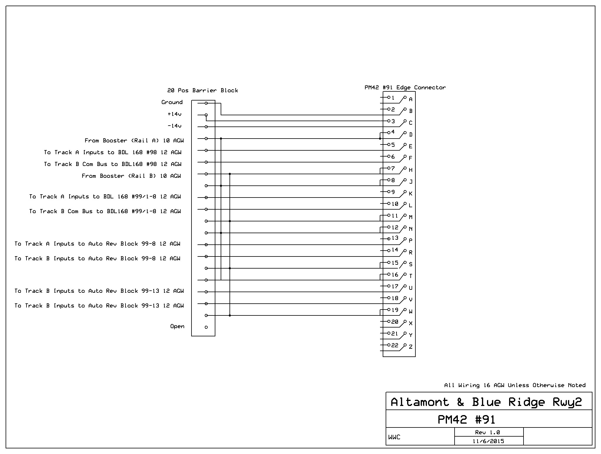
The Digitrax system I use is pretty straightforward in this regard. It
employs 2 PM42 power managers, each with four outputs. Each output can
be configured to power a short circuit protection power
district that shuts down when it encounters a short without shutting
down other power districts, or
to power a district that reverses polarity upon encountering a
short. To create the detection blocks, Digitrax systems use the
BDL168 card. This device has four inputs that take power from a PM42
district. Each input on the BDL168 has 4 outputs, so the unit will
support 16 detection blocks. In a normal situation a BDL168 will have
all 4
inputs fed by the same power district output from the PM42,
resulting
in a power district with 16 detection blocks. This is the
case in 4 of the power districts above (Green, Purple, Brown, and
Blue). To create power
district Yellow, I feed inputs #1 an #2 of a BDL168
from district #1 of a PM42 to create 8 detection blocks. To
create the two power
districts Red, I feed input #3 and #4 of the same BDL168
from the same PM42 using the outputs for power districts #2 and #3,
which have been configured as auto-revesing districts thus creating 2
auto-reversing power districts each with a potential of up
to 4 detection
blocks. In this case I have only a single block per reversing
district, each powering and providing detection for a single polarity
revesing
loop. (Note: I later scrapped the idea of using the BDL for
auto-reversing because it uses four detection blocks for each
auto-reverisng circuit and, as I revised the track plan, I found I need
these extra eight detection blocks. I therefore decided to use a
separate auto reversng device on the two yard crossover blocks
that require
auto-reversing. (See post of 2-6-2016)
The Naming of Power Districts,
Detection
Blocks and Turnouts
8-2015
The TrainController software I use allows you to name detection blocks
whatever you like, but it will require you to create an internal
digital
address for each block according to a specific convention. Most model
railroaders like to name blocks descriptively - names that suggest the
block's location on the layout. For example if I Number tracks
sequentially in a section beginning with the track closest to the edge
of the backdrop, I might choose to
call the block that is the section of track closest to the backdrop at
East River "East River#5" or ER5. Or
I might number the tracks in the Altamont Yard ladder such that the top
or Northern most track would be "AY#1;" the next track down
would be "AY#2" etc.
Of course, what you name the block does not matter to the digital
control system. It has its own set of addresses. For example the track
that we called "ER#5" will, according to the Digitrax rules
as applied to my current wiring scheme, have a digital address
"97-4." That is, it is output #4 from the DBL168 which I have
designated and programed to have Board Address #97. If I name the Power
District using the board numer of the BDL168 that they supply, this
block name will also tell me the powerdistrict that the block in. In
this case Power District #97, which is PM42 #90, output #3.
So the approach I think I will take to naming my blocks will include
location and digital the block address. In the
above
example, the North Bound Outside Line block at East River will
be called "ER5/97-4." A bit cumbersome
perhaps, but it covers the all bases.
Likewise, in TrainController turnouts can be called whatever your like,
but each turnout must have a unique digital address (any number
from 1 to 2048) programmed into the DS64, a stationary decoder
that can control four Tortoise switch machines. Following the same
convention, I will name my turnouts to reflect location, destination,
secondary location, DS64 board number and its output number, and the
digital address. I
plan to use the digital addresses 1100 to 1600 for turnout address
according to the following scheme:
1100 - Fitzhugh
1200 - Westridge
1300 - East River
1400 - Little River
1500 - Altamont Yard
1600 - Altamont Terminal
So
the turnout at Fitzhugh that shunts trains to the AltamontCity High
Line will
be Fitz/AltamontCity/57-3/1105 assuming it is power by DS64 #57,
output
#3 and assuming I assign the digital address 1105 to this output.
In
another example, the crossover from one mainline to the other
to allow access to and from the northern entrance to the depot sidings
a East River will be ER/Crossover/Side/North/xx-x/1301A&B (where
xx-x is a holdong place for the DS64 board numer and its output number
(1-4), and "A&B" because this DS64 one output will operate
both turnouts of the crossover simultaneously.
Note: I later ame to find that four digit DS64 address (that is
addresses above 1000) can only be programmed and accessed using a
computer program like TrainController and are not accessable via the
Digitrax throttle, So I changed the address ranges above by
subtraccting 1000. Thus I will use address 100 to 600 not 1100 to
1600.
If I use these block and turnout names in all
wire and BDL168 terminal block and DS64 output labeling and in
under-the-bench
Tortoise and
dropper labeling, it will
greatly facilitate troubleshooting and other servicing.
What Do I Need?
8-12-2015 (updated 9-20-2015)
A key part of the model railroad planning process involves
selecting what kind of components one wishes ot use on a new project,
calculating the quantities needed, finding the best sources, and
preparing some kind of budget. As the foregoing text details, I have
pretty much decided what components to use and where to get
them. I need now determine the quanties required and what the
cost will be.
I'll start with track. The CAD layout design software I use has a neat
little inventory
feature. It totals up exactly what your layout will require in the way
of track and turnouts. According to the current design I will need the
following to build the A&BR2 if I am able to salvage all to the
track and turnouts from the current layout:
A&BR2
Turnouts:
27 | Large Left
26 | Large Right
15 | Medium Left
7 | Medium Right
Track:
9334 inches N Flex Track |
A&BR current layout
Turnouts
15 | Large Left
13 | Large Right
13 | Medium Left
10 | Medium Right
Track
4467.956 inches N Flex Track |
Needed
Turnouts
12 | Large Left
13 Large Right
2 | Medium Left
0| Medium Right
Track
3866 inches N Flex Track
|
I see no reason why I can't reuse all of the the Peco Code 55 turnouts
from the current layout, and certainly a large portion of the track
will be reusable, perhaps 90%. So I will need to purchase only 7 large
left, 9 large right, and 8 medium left turnouts (~$540), about
24
more Tortoise switch machines (~$388), and
about 3866 inches of N Flex track (that's 107 3 foot
sections or about 3 boxes of 30 or about ~$500). Total =
$1428.
As far as Digitrax control devises go, I am pretty well set. I have the
5 BDL 168 block detection cards (4 on the layout and 1 spare), 14 DS64
stationary decoders, 3 SE8C signal control cards, 2 PM42 Power Manager
cards, 1 remote loconet plug in port, and a DCS 100 Command Station. I
have not done any planning so far regarding signal placement, but, if I
put any signals at all in the yard and the main passsenger terminal, I
am
pretty sure I will need at least 1 more SE8C signal card (~$100) to go
with the 3 I already have, and
maybe 15 more masts (~$50), also one more remote plugin station (~$13)
and
quite possibly a BD150 booster (~$150), plus maybe 6 more DS64s ($150).
Total = $463.
Given the large size of the new trainroom this project is going to take
alot of wire, and I seriously doubt that I can salvage too much from
the current setup - perhaps 300 feet of red stranded 12 AGW and a
like amount of red and black stranded 16 AGW. Maybe a little more, but
I do not want to get into trying to splice together shorter pieces. It
is better just to buy new, and it is best to get it all up front to
take advantage of quantity discounts, which, when it comes to wire are
sizable. So, how much will I need? Surely it is best to order it all up
front in bulk to take advantage large spool pricing and probably avoid
shipping charges.
For power buses I use stranded 12AGW building wire. Assume the average
12AGW mian line red bus run in a trough is 2/3 of the length of the
room, that is to say 30 feet. There are 44 main line blocks, so that's
1320 feet. The remaining 28 blocks are for ladders and the turntable
fan. These will require much shorter runs, say 10 feet on average, so
that's another 280 feet. Add another 200 feet or so for PM42 to BDL168
lines, for the main undetected power bus, and for PM42 to main
booster lines, and we get a total of 1800 feet, less the 300 salvaged
from the current layout gives us about 1500 feet or 3 500 foot spools
(~$160). Turnouts and undetected routes will get power from the
undetected power bus which is
part of the additional 200 feet I added, so I need no additional heavy
wire for them.
For black 12AGW, I'll need on average 30 feet for each power zone or
reversing loop, that is 180 feet plus the 200 feet for the main etc.
that is 380 feet. So better get 1 500 foot spool of black 12 AGW
(~$53).
For feeders I use stranded 16AGW automotive wire. I'll need about 3
feet on average for each power block connection and 3 feet for each
turnout. I will connect to the power blocks every 3 feet or so.
Mainline power block might average 40 feet (10 connections each
times 44 mainline blocks times 3 feet each = 1320 feet). Ladder power
blocks will probably average about 8 feet (2 connections each time 28
ladder blocks times 3 feet = 168 feet). There are 61 turnouts, so time
3 that's another 183 feet. Plus 200 feet for short run connections to
BDL168 and PM42 etc. In all, I estimate I need 1663 feet of red and of
black. So let say 6 500 spools all together, 3 red and 3 black ($330).
For lights I'll also use 16 AGW automotive wire in green and blue. I
don't really need wire this heavy to run my LEDs, but automotive wire
or "primary" is actually cheaper than lower gauge "hookup" wire. At
this stage I can't estimate the amounts I'll need but I'm sure it will
be over 500 feet. So 1 each blue and green 500 foot spool at (~$110).
For power droppers I'll use 20 agw insulated solid copper. 2 100 foot
rolls should do it (1 each red and black for track power, and 2
rolls of 22agw solid copper insulated green and blue for lights
droppers) (~$55). Total ~$700.
I'll also need some cable ties.
I'll also need more loconet cable and more RJ12 connectors. 100 feet 6
conductor phone wire (~$10) and 50 RJ12 Connectors (~$15).
61 Edge connectors for the Tortoise Switch Machines.(~$180).
Barrier blocks pending and inventory of the current layout. Need 63 8
position, 5 20 position.
For lighting structures I'll need about 200 each 5mm warm
white LEDs (~$10). I will also purchase a 5 volt power supply. The
power supply I have my eye on right no has both 12 volt 6 amp output as
well as a 5 vlt 24 amp output. $40.
For
everything except loconet and the Tortoises I will use hard
solder connections insulated with electrical tape or wire nuts. The
Digitrax control cards of course have edge connectors, and I will wire
short lengths of 16 AGW to the pins of these edge connectors and then
marry these short "pigtails" to the heavier wiring of the rest of the
layout
using the Barrier Blocks. I will install individual block on/off
switches in these "pigtails." I have appropriate toggle switchs on hand
from an old non-DCC layout, so toggles are not on my list. (Note: I
later decider not to add these switches.)
I'll have contractor erect the interior walls with their 48 inch
radius corners and install all the room lighting, so none of that is
part of my shopping list. The next item to estimate then, is lumber
for the benchwork: 8 8' 2x4s , 18 8' 1x6s, 21 8' 1x4s, 8 finish
grade 3/4" plywood
4x 8 sheets and 8 1/2" homosote 4 x8 sheets. Black formica
laminate 2 each 12x 30" sheets = $140. A quick look at the
Lowes web site for prices, some quick calculation and, voila: ~$790.
I'll also need some more black skirts with velcro strips~$300, and 100'
feet of 1" stick-back velcro ($30).
I do not think I will try to reuse rail joiners, so with 64 turnouts
I'll need 400 plastic insulated Peco joiners plus maybe 30 more for
other block isolation, and perhaps an equal number of Peco metal
joiners. Let's say 16 packages of 24 metal joiners @ &2.50 and 32
packages of 12 plastic @ $2.50 or a total of $112.
Likewise I don't think it is a good idea to try to reuse cork roadbed,
so I'll need 10,500 inches of the stuff; that is about 900 feet
or 300 strips or 6 boxes of 25 strips at $16 per box = $96. Plus
19 large left and 19 large right and 20 medium left and 8 medium right
cork turnout pads @ about $2 each for total of about $112. (Note:
I later decided not to use the precut raodbed and switch pads. I'll use
1/8" corl sheet andcut my own.)
Glues and adhesives (3M Adhesive spray, CA, 1 gal Elemrs white glue, 1
quart water based contact cement for glueing down roadway and
paving styrene sheets, and a large squeeze bottle of yellow carperters
glue for homostoe mountan frames), nails and screws (long and short
sheet rock screws, small brads with flat head for screen, small wood
scres for securing circuit boards and tortoise machines), plastic
screen, .40 sheet styrene, (about $100)
In the computer area, I need several things. First, I need to upgrade
my TrainController software from, Silver to Gold, the highend wham-o,
expert version that I will need to take full advantage of the +Net
software I need to buy in order to employ two computers as
previously alluded to in this blog. The upgrade and the +Net software
will cost me about $600. I plan to do this soon so I can get
things running on the current layout. That way I will be fully
conversant with this new technology by the time I start wiring the
A&BR2.
I also will need a second computer. My thinking here is to get two
inexpensive matching 4 gig refurbished HP desktops running windows 7 or
8 (about $200 each) so I will
have matching computers to sync up via +Net when I get to that. This
along with two small new monitors will make a slick control desk for
the new layout. Software, computers, monitors, additional loconet
interface box, keyboard and mouse will probably total in the area of
$1400.
If my sound scheme works I'll need another 7.1 sourround USB Box ($32)
and 3 more desktop Speakers ($25) and pretty good deal of some
speaker wire ($100).
4 gal white primer, 3 gal sky blue, 1 gal white, 1 gal black = 9 gal @
~$35 = $315. This will cover the materials I need to paint the graded
blue sky backdrop with some nice clouds dry brushed onto it. I already
have the brushes and multiple rollers and pans I need to do the graded
shading of the sky (slowly getting lighter as it approaches the
horizon). Dry brushing very convincing cloud forms is easy once you get
the hang of it, but there is a trick to it. More on that later. The
backdrop will also get a few rows of distant mountains, but I
generally just lightly pencil their outline on the wall to begin with.
I will paint them later, one section at time, when I know exactly
what will go in front of them. (see "Marrying the Backdrop to the
Layout" elsewhere on this site.)
So about $6400 in all to paint the backdrop,
build the bench work, lay the track, wire, and computer and sound
equip a 40 x 20 foot layout with 51 turnounts, 61 blocks, and over 850
feet of track. This does not include the interior backdrop walls and
the room lighting and sofits, the HVAC and AC wiring, which the
contractor will see to. It also assumes that I have salvaged
from my current layout almost all of the turnouts I need along about
40% of the track, almost
all the DCC devises and software, and a little wire.
Selecting Vendors
8/13/2015
I've done a little on line shopping this morning to check prices and
inventories. I'll probably use the following vendors. most of whom I am
already familiar with:
M. B. Klein
("Model Train Stuff" on line).
Peco track and turnouts, the rail joiners, and
the Digitrax devices, cork roadbed and turnout pads, Tortoise switch
machines and Tortoise edge
connectors. I have dealt with this company for years. Their prices
are good, and their service is excellent. With such a large order, I
hope to negotiate a small discount and get free shipping. I also need
to check their prices against Amazon who has listed some incredible
deals on model railroad products lately.
ActivePowerSports online. This
is new online vendor, and thier prices on man items are a bit better
than even Klein, but the sevice and selection is not as good.
Lowes
Lumber, 12 agw building wire, large cable ties, glue, nails, screws,
and paint
Appalachian Supply (my local
lumber dealer)
Homosote and Plywood
Dell City.org
Wire, speaker wire, hookup wire etc. (I will probably get the 12 agw
from Lowe's on line and have it shipped to the store near me, and I'll
get the 16 agw from Amazon.)
US Plastic Corp
Styrene sheets
Amazon.com
5mm LEDs, desktop speakers, and Encore USB Surround Sound Box. I
generally first check Amazon for anything I need. With Prime I get free
shipping, their prices are generally the best, and they have a lot
of electronic stuff.
Jameco Electronics
loconet cable, RJ12 connectors, and barrier blocks, small cable
ties
Best Buys (on line)
Refurbished computers and monitors etc.
Further Tweeking of the Track Plan
8-14-2015
I sketched in locations for the depots at East River, Westridge, and
Fitzhugh this morning. The depot at Fitzugh is an on-the-mainline
stop. It has no siding, so no track changes were needed other than to
separate the to mainline tracks enough to allow a long passenger
paltform to fit in between. However, the
depots at East River and Westridge do have sidings, and so I added
cross-overs to accommodate trains approaching from and departing to the
mainline track
away from the sidings. I also added a crossover near Little River
to allow the EB highline to access the Altamont City line. Finally, I
am thinking about adding a streetcar line down the center of the main
street in Altamont. I adjusted
block locations accordingly and
also
adjusted my shopping list and the budgets above to reflect these
additions.

|
This is the kind of tweaking that comes
from thinking about the plan and tracing imaginary train routes. The
added crossovers allow access to sidings located on the opposite side
of the other parallel mainline track. |
Tweaking the Wiring Schematic
8-15-2015
I think the track plan is now close to the way I want it, but I'm still
going over the positioning of the blocks on the A&BR2. I've
done a little more tweaking, and shuffled the power districts a
little. One of the the things that worries me a little is the
length of some of the wire runs. A few of these runs are over 40 feet,
and most experts including Allan Gartner, say 30 feet is about the max
one should go without adding more boosters. Are my blocks so long
that
I am asking for inductance and termination problems? Will I need an
additional booster?
I think I have hit on a solution. If I place the booster or boosters in
the center of the room under the central section of benchwork and
centrally
locate the two PM42s along the north and south edge of
the central bench section, and if I install under-the-floor troughs
from the center of the central bench to both the north wall bench
and the south wall bench, I can then place all BDL168 block detection
devices in the center of their respective benches while, at the same
time, holding the wire runs from the PM$2s to the various BDL168s to
under ten feet as recommended buy Digitrax. Feeding buses like
this out from the center will
hold almost all of my runs to under
30 feet. Most will be considerably shorter.
This way, if I still happen to need a second booster, I can
install
it easily right
next to the first one. I need only wire them together and then have one
feed each of the two PM42s. This will split the overall load almost
equally.
The revised schematic below reflects all these changes and
color-codes
the 5 power districts (Green, Blue, Purple,
Brown, and Yellow) and the two reversing tracks
(Red). It is
still not of high enough resolution to allow a detailed analysis of
the layout wiring nor does it detail the turnout decoders or power
buses or or signal logic cards and feeders or all of the
track connections. All of this will be detailed later, when I create
separate wiring schematics for each power district.
 |
More Work with Block and Turnout Names
8-17-2015
I've spent more time honing the naming of detection blocks and turnouts
and labeling these blocks and turnouts out on my schematic. In
overview, things look pretty messy with all of this text on the
schematic; but when
I get down to making a block list and doing individual schematics
for each power district,
things will look much more orderly. I will use these individual
schematics as a guide when I start wiring, and the block lists to
create computerized labels for wires,
barrier blocks, and digital devices. Having a comprehensive plan and
labeling as you go are essential when it comes to keeping things
straight once
wiring begins.
Block Names and Locations Overlaid on Track and Wiring Schematic. When
rendered in overview like this, the scale is too small to be of much
practical use, but this gives a general idea of what the schematic
looks like.

|
Turnout Names and Locations Schematic Overview. Notice I have used the
notation xx-x where
the DS64 board number and output number will go. I suppose I could
assign these number now, but I think it is best to wait and assign them
as I install and hook up the DS64 swithch machne control decoders.
With such long and descriptive turnout names, using
the full name to name the turnouts in TrainController will
result in something of a mess. So I'll just
use the 4 digit digital addresses to name the turnouts in
TrainController. I'll use these longer descriptive names, which
include the digital address, for
all wire and devise labeling.
Doubts
8/18/2015
Ever since I started this blog, I have been having nagging doubts about
this project. It is not so much that I am unwilling to demolish the
A&BR1. I can dealt with that. No, my concern rises from the
notion that the A&BR2 might be bitting off a little too much.
Simply put, I
fear that it might just be to big, When the interior
backdrop walls are
complete, I will have an empty trainroom that is 35' x 17.5' - over 600
square feet - a room that will accommodate over 125 ruining feet of
bench front - over 3 times the size of the A&BR1 - almost 4 miles
in N scale - enormous. On the face of
it, this actually sounds pretty good, but when I stand in my current
20' x 12' trainroom, which is actually pretty big, and try to imagine
an empty room almost twice as long and twice as wide, I feel a
little overwhelmed. It is too much?
Too much for what? Too much to finish before I die? Too large to
actually work? So much track to lay, wire to run, and scenery to
build that I will grow tied of it?
Well, perhaps, but there is another side of me that says, I need this
project to keep me engaged in something, to inspire me and drive me on,
to maintain my vitality, happiness, and sence of purpose - even to add
years to my
life.
It's a conundrum.
Upon refection, I think it comes down to this: build the
A&BR2 or find another passion to occupy my thoughts and
actions in retirement. I have been pretty good at finding new
passions ever since I retired in 1996. For years I wrote books, but the
publishing industry changed so drastically that this became sort of
pointless. For a while, I spent time learning C# and programming
multi-relational databases using SQL, but I am continually searching
for applications, and I have reached the point where I can't really
progress in any meaningful way without some help, ie. going back to
school, which I really
don't want to do. For a short while I dabbled in robotics and did I/O
programming to control various devices, especially servo motors, but
again the lack of applications seemed to be a road block.
So, in the absence of anything else, I might just need this project.
Whatever the case, I plan to follow it along and just kind of see where
it leads me. The real decision will come when my architect and I
complete the plans for the new building. At that point, I will have to
do some real soul-searching. What will it cost? Should I build it? I
can make all kinds of rationales for the the new structure, but the
real truth is: if I build it, my central, underlying motivation
will be to create the A&BR2.
Block Lists
8/19/2015
I am now starting to get pretty comfortable with my track plan
and my block placements. Certainly there will be a few changes as I
continue to think about the schematic, and probably I will make a few
more changes when I begin to trace the trackplan onto the layout
benchwork. But what I have now is pretty close, and so I can go ahead
and create a list detailing the configuration of each of the
5 BDL168 16 block detection cards.
|
Alt1/95-1
|
|
Alt2/95-2
|
|
Alt3/95-3
|
|
Alt4/95-4
|
|
Alt5/95-5
|
|
Alt6-South/95-6
|
|
AltCitySouth/95-7
|
|
Fitz4/95-8
|
|
Fitz3/95-9
|
|
Fitz2/95-10
|
|
Fitz195-11
|
|
WR1/95-12
|
|
WR2/95-13
|
|
WR3-Side/95-14
|
|
ERCrossing2/95-15
|
|
ERCrossing1/95-16
|
|
|
TT/Bridge/96-1
|
|
AT/Shops1/96-2
|
|
AT/Shops2/96-3
|
|
AT/Shops3-Main/96-4
|
|
AT/Shops4/96-5
|
|
AT1/96-6
|
|
AT2/96-7
|
|
AT3/96-8
|
|
AT4/96-9
|
|
AT5/96-10
|
|
AT6/96-11
|
|
AT7/96-12
|
|
AT8/96-13
|
|
AT9/96-14
|
|
AT10/96-15
|
|
AT11/96-16
|
|
|
LR1/97-1
|
|
LR2/97-2
|
|
ER5/97-3
|
|
ER6/97-4
|
|
ER1-Side2/97-5
|
|
ER2-Side1/97-6
|
|
ER3/97-7
|
|
ER4/97-8
|
|
ERCrossing3/97-9
|
|
ATLoop/97-10
|
|
ATNorth/97-11
|
|
ATSouth/97-12
|
|
ATSouthSiding/97-13
|
|
ATConn/North/97-14
|
|
ATConn/South/97-15
|
|
AY/Lead/97-16
|
|
|
Alt6-Center/98-1
|
|
AYSouthWB/98-2
|
|
AYSouthEB/98-3
|
|
AY8/98-4
|
|
AY7/98-5
|
|
AY6/98-6
|
|
AY5/98-7
|
|
AY4/98-8
|
|
AY3/98-9
|
|
AY2/98-10
|
|
AY1/98-11
|
|
AYNorthAD/98-12
|
|
AYNorthWB/98-13
|
|
AYNorthEB/98-14
|
|
AltCityNorth/98-15
|
|
Alt6-North/98-16
|
|
|
TT1/99-1
|
|
TT2/99-2
|
|
TT3/99-3
|
|
TT4/99-4
|
|
TT5/99-5
|
|
TT6/99-6
|
|
TT7/99-7
|
|
TT8/99-8
|
|
AT/Cross/99/9 Rev
|
|
Empty
|
|
Empty
|
|
Empty
|
|
AY/Cross/99-13
Rev
|
|
Empty
|
|
Empty
|
|
Empty
|
|
BD4
StreetcarNorth/BD4-1
StreetcarNorth/BD4-2 |
In all, 76 detection blocks, on 5 regular short circuit
protected power districts and 2 auto reversing power districts, and one
BD4. On a
large layout, I cannot overemphasize the importance to this kind of
carefully considered pre-planning when it comes to block naming, block
powering, and especially block placement. There is a lot
going on here, and this kind of planning and documentation will really
help keep things straight once wiring and labeling begins. What is
more, these kind of schematics and lists along with thorough wire and
device labeling will prove invaluable during
troubleshooting and service once the layout is complete.
Turnout Lists
8-20-2015
Similarly I have prepared a list of Turnouts. there are 68 in all, so
I'll need 17 4 output DS64 stationary decoders, plus I'll need probably
three more DS64s to control lighting relays, crossing flashers. So 20
all together. Again, notice I have entered these names using "xx-x"
placeholders where the DS64 board number and output will go. I will
number DS64's sequentially around the layout as I install them
beginning with the board number 50. So I'll have numbers 50
through 69
each with outputs 1-4. Note: The listing below is an early iteration
does not exactly reflect the finished plan, nor does it incorporate the
subsequent three digit numbering scheme, but this at least gives a good
idea of my method.
A&BR2 Turnout list (68)
Trunouts at Fitzhugh (7)
|
Fitz/Crossover/ATConn/xx/x/1101-A&B
|
|
Fitz/HY2/xx-x/1102
|
|
Fitz/HY1&2/xx/x/1103
|
|
Fitz/Crossover/HY&Axx-x/1104-A&B
|
|
Fitz/AltamontCity/xx-x/1105
|
Turnouts at Westridge (6)
|
WR/Side/North/xx-x/1201
|
|
WR/Crossover
/Side/North/xx-x/1202-A&B
|
|
WR/Crossover/ERSide/South/xx-x/1203-A&B
|
|
WR/Side/South/xx-x/1204
|
Turnouts at East River (8)
|
ER/Crossover/Side/North/xx-x/1301-A&B
|
|
ER/Side1&2/North/xx-x/1302
|
|
ER/Side2/North/xx-x/1303
|
|
ER/Side1&2/South/xx-x/1304
|
|
ER/Side/South2/xx-x/1305
|
|
ER/Crossover/WRSide/South/xx-x/1306-A&B
|
Turnouts at Little River(7)
|
LR/Crossover/AltamontCity/xx-x/1401-A&B
|
|
LR/AltamontCity/xx-x/1402
|
|
LR/Crossover/AY/xx-x/1403-A&B
|
|
LR/Crossover/AYLead/xx-x/1404-A&B
|
Turnouts at Altamont
Yard (19)
|
AY/LeadToADNorth/xx-x/1501
|
|
AY/SouthAD/West/xx-x/1502
|
|
AY/Crossover/LeadToADSouth/xx-x/1503-A&B
|
|
AY#1/xx-x/1504
|
|
AY#2/xx/1505
|
|
AY#3/xx/1506
|
|
AY#4/xx/1507
|
|
AY#5/xx/1508
|
|
AY#6/xx/1509
|
|
AY#7/xx/1510
|
|
AY/ADNorth/East/xx-x/1511
|
|
AY/CrossoverRunAround/xx-x/1515-A&B
|
|
AY/ADSorth/East/xx-x/1512
|
|
AY/HY2/xx-x/1513
|
|
AY/HY1&2/xx-x/1514
|
|
AY/Crossover/ATConn/North/xx-x/1515-A&B
|
Turnouts at Altamont Terminal (21)
|
AT/SouthSide/East/xx-x/1601
|
|
AT/ShopsTTMain/xx-x/1602
|
|
AT/Shops1/xx-x/1603
|
|
AT/Shops2/xx-x/1604
|
|
At/Shops3/xx-x/1605
|
|
AT
SouthSide/West/xx-x/1606
|
|
AT/Cross/South/xx-x/1607
|
|
AT/#1/xx-x/1608
|
|
AT/#2/xx-x/1609
|
|
AT/#3/xx-x/1610
|
|
AT/#4/xx-x/1611
|
|
AT/#5/xx-x/1613
|
|
AT/#6/xx-x/1614
|
|
AT/#7/xx-x/1615
|
|
AT/#8/xx-x/1616
|
|
AT/#9/xx-x/1617
|
|
AT/Crossover/RunAround/xx-x/1618-A&B
|
|
AT/Entrance/North/xx-x/1619
|
|
AT/Entrance/South/xx-x/16
|
Again this list will aid in
keeping things in order when wiring begins and when the numbers are
filled it will also be helpful in layout servicing and
troubleshooting.
Creating a Switchboard in
TrainController
8-21-2015
Now that I have a track plan and all of my block names, I can begin
creating a switchboard in the new TrainController Gold software that I
have just downloaded from Freiwald Software. I have not yet purchased
the license for Gold, but Freiwald allows you to use the software in
an off-line, demo mode for 30 days. You can create all of
the objects needed to run your railroad, and even run trains on the
screen in a simulated mode. The only thing you cannot do in this demo
mode is connect to your layout. You need a license for that. What is
more, the 30 limit is calculated to include only the days you make
changes to a file, so it is really quite a liberal trail period.
I am currently licensed to use the Silver version of TrainController,
and designing the switchboard in Gold is pretty much the same as
Silver, so there was no real learning curve to get beyond. In Gold
there are some much more sophisticated methods for handling turn
tables, but trying to learn all that now with no real layout to test it
on seemed risky, so I used the a turntable bridge block connected to a
small ladder, just the way I have been doing in Silver. It may look a
little clunky, but it works. Anyway, the below
switchboard only took a few hours to create and a good portion of
that was
spent pasting in the block names. I have not yet put in my turnout
names, but
the software assigns a working name to each object at the time it is
created. So I can go back and put in my own unique turnout names any
time I like.
 |
Still
More Track Plan Tweaking
8/22/2015
Unlike the renderings from my XCAD model railroad design software,
which
are quite
detailed and strictly scaled, the rendering of the TrainController
switchboard is a highly simplified block diagram of the track plan.
This stylized format makes it much easier to evaluate the flow of the
layout.
Looking at the above switchboard, I see two areas that still need
attention. Both the North and South entrances to Altamont Yard are not
quite right in the way they tie into the auto reversing crossing
track. Designing a yard between two double track mainlines with two
AD (arrival and departure) tracks and an auto reversing crossover is
tricky. Below are before and after renderings detailing these changes
using the TrainController switchboard to present the simplified
overview, and closeup of the detail using XCAD.
Notice that this change required the creation of an additional block,
the deletion of 3 turnouts and the addition of four new turnouts. All
my BDLs are full, so I did away with the block Alt6/Center.98-1 and
used that position to create the new block for the new block I created
when I split AYSouth/CrossAD into two blocks: AY/SouthAD and AY/Cross,
the reversing section.
The track
section that was Alt6Center will now be an undetected route.
before
 |
after
 |
before
 |
after
 |
In additon I have added a runaround for the North AD Track. I
will update both the block list and the turnout list, although I
see no need to post the updated lists or the revised XCAD rendering
here.
Below is a rendering of the revised TranController switchboard
reflecting all of the changes.
 |
Thinking About
the Yard
8/25/2015
I have been busy entering turnout names and labels into the
TrainController Switchboard. I have also been contemplating Altamont
Yard to make sure my tweaking is done. I reproduced a closeup of the
yard switchboard in a separate jeg file and pasted some labels
over the top in
order to define yard functionality. This helps to evaluate the way
traffic will flow. Here is the completed jeg showing the yard between
the two double track mainlines, with two separate arrival/departure
tracks, a yard crossover for correspondence between the North and the
South mainline tracks, 2 run arounds, a staging track, 4
classification tracks, a caboose track and an auxiliary engine service
track.
Remember, TrainController Switchboard schematics are not to scale, so
don't worry if, for example, the South AD track looks a little
short. On the scaled XCAD schematic it is not. It is actually about
quite a bit longer than my longerst train. Ideally, these AD tracks
ought to be something on the order of twice as long as the longest
train on the layout, and any reversing crossover should be at least as
long as the longest train.
 |
Signal Placement and Terminal Track Plan
8/26/2015
Over the last few days, I have been fooling with signal placement.
This will require a great deal of thought, but I think it is best
to just sketch out something to begin and tweak it as I go along.
Accordingly, I have entered my initial mainline signal plan onto the
TrainController switchboard. Although stylized and not to scale, this
switchboard offers the most clear and readable representation of
my layout. Each little
green signal icon represents one three aspect signal head. As you can
see, I will be using double headed masts with 3 aspect heads
exclusively (the top head always shows the mainline ahead and the
bottom head the siding ahead). Conditions for each of these signal
heads will be programmed into TrainController later. The resulting
logic will
determine whether each head is red, yellow, or green depending on block
occupancy and on turnout positions ahead of the signal. When wiring and
programming are complete, these icons will change color in sync with
the signal heads on the layout. (Note: for a more complete discussion
of signals and signal placement see entry of 2/24/2016)
I also made a few changes to the track plan at Altamont Terminal,
altering the entrance to the ladder and the positioning of the crossing
reversing track to streamline entry into the ladder and to more
exactly reflect the plan in the XCAD schematic.
 |
Another Design
8-30-15
Further discussions with my architect have resulted in an altered
design for the new building that will house the train room. Trainroom
dimensions have shifted, and I have completely re-done the XCAD
schematic to shoehorn my trackplan into a different space. There are
some compromises regarding the access aisles, but in general it all fit
pretty well in what has now become effectively a 31' x 19' space.
Since
it is a not-to-scale, stylized representation of the layout, I was able
to alter my TrainController switchboard to reflect the new plan without
much effort, and with a few exceptions, my turnout and power block
lists
remain the same. All of this serves to remind me that, at this point,
my designs are only preliminary renderings; and until I get finished
architectural drawings, I will not be able to create a
"down-to-the-inch" track
plan.
Nonetheless, every re-working of the track plan, yields positive
results. In altering the plan to fit into a smaller space, I made some
changes, which I will incorporate into my original design should I go
back to the original room dimensions. Notably, I have cut back on the
number of ladder tracks at Altamont Terminal, changed the access to one
of the hidden sidings under Altamont City, added a few spurs, and
moved one siding. All of these changes are imporvements,
regardless of final room size.
Below is the XCAD rendering of the
revised trainroom.
 |
September
2015
Further Considerations Arising from a
Smaller Trainroom
9-1-2015
The proposed new trainroom is about 33' x 19, that is 627 square feet.
The original design totaled almost 595 square feet. So I have roughly
the same, but with a little less length and a little more more
width. This new plan cuts the amount of track needed by about 1300
inches
(about 15%), and it will probably reduce the amount of red bus
wire I need
by about 300 feet or so, so I can get 5 boxes of track instead of 6 and
perhaps 2 500
foot rolls of 12 agw wire instead of 3. The change in the amount of
black bus wire is minimal and the requirements for red and black 16 agw
feeder wire will not change much. Likewise the requirements for loconet
cable and dropper wire are inconsequential.
In the original design, I was right out on the edge when it came to the
length of the longest bus runs. With this new plan, I have probably
reduced the
risk of creating any of the problems that can arise from
overly
long bus runs.
On the whole, I actually feel pretty good about the altered the
trainroom. I think the concept of the trackplan is still fine, but
whether or not cramming all of the features of the original layout into
a
slightly narrower space will appear over-crowded is a question
that can only be
answered when track laying begins. I suspect that there is still plenty
of space for everything, but should things look cluttered when I begin
to lay track, I'll re-assess the trackplan.
There is always give and take between the track plan and track laying,
so this kind of flexibility is a good thing. For example, when I begin
to lay track, I get a feel for the scale and the look of of things
that cannot be gleaned from an on-paper plan. At this point, I can
begin to make some fundamental decisions about the exact size and shape
of topographical features and about the placement of key structures.
This will require sketching the topo of mountains and
roads, etc. onto the benchwork and sometimes tweaking track
routing to make things work exactly right. It will also
require looking up the footprint dimensions of key structures and
altering track spacing as needed.
Still MoreTweaking of the Benchwork and
Track Plan
9-6-2015
The change in trainroom size has precipitated numerous changes to
the track plan. Although in general layout and function remains
pretty much the same,
many details had to be tweaked to accommodate the reconfigured
space. Along with these changes have came improvements. For example, I
moved the entrances to Altamont Terminal from the hidden yard under
Altamont City and placed them on either side near the entrances to the
hidden yard. This facilitated a consolidation of blocks using only
three, where originally I had used five. Likewise, I added a crossover
to access the hidden yard siding entrance at Fitzhugh, and consolidated
the
block placement in that area thus creating two more free blocks. I used
the four extra blocks for the streetcar line (2) and for the leads on
the southern runaround at Altamont Yard ladder tracks (2). All this
switching of blocks necessitated a reworking of the BDL168 wiring and a
more logical re-grouping of blocks within the various power
districts. Here is the revised switchboard for the new trainroom
configuration.
|
Turning my attention to the benchwork, I removed the walls at the
entrance to the trainroom, thus eliminating
two sheetrock backdrop radial walls. I think I will achieve a cleaner
look with the mountains at Fitzhugh and at Westridge nestled up against
a higher, contoured faisure board instead of having a large radial
wall
protruding out into the room. I will still have some access inside the
tunnel from behind the backdrop wall, although this will be more
limited than in the
previous design. I will probably have to make part of the mountains
removable as
I have done in the the corners of the A&BR1. The sketch below
illustrates my general intent for the revised entrance.
 |
Finally, I reworked the benchwork to employ standardized one foot radii
in all the bench corners along the cental asiles. I also
located the four under-the-floor wire conduits. Below is the
revised
trackplan and benchwork schematic.
(Note 3-3-2016: The problem here is still the 2 1/2 foot wide aisles.
As noted in the final, I as able to expand these out to 3 feet, hich is
in my mond the minimum acceptable width.)
 |
Accessing the Hidden Yard
9-7-2015
One of things I most want to incorporate into my new A&BR2 is good
access to all track in tunnels and hidden yards. The large
removable homosote framed mountain forms I have used on the
A&BR1 work well enough, but they are cumbersome to remove and
replace. I plan to use a similar scheme to assure full access to the
corner tunnels of the new room and in the tunnels in the
turnarounds by the door. There
will be pretty good access to these areas from behind
the backdrop, and so there should be fewer occasions when I will need
to
remove the mountains. Still, in the case of a sever track maintenance
problem, I will want full access to all areas, and so I will add the
removable mountains in some of the corners just to be sure I can
really open everything up should the need arise.
As for the hidden yard, I plan to build Altamont City on a series of
hinged covers that will lift
from behind the backdrop to fully expose the under-the-city mainlines
and holding tracks. The schematic below details this plan. The scale
reads in feet, but here it is to be interperted in inches, so it
details the
5" elevation of the siding through the city, and the street plan with
spacing dimensions for all lateral streets as well as the grade
angles of the cross streets. This hinged "lid" with the city atop will
traverse the portion of east wall of the new train room that is
accessable from behind the backdrop. The same design but with the
hinges on the other side will travese the short section fot he
east wall that is against the block outside block wall. This shorter
section will not have the tree lines attached and will hinge up at he
wall for acess to the track undeneath from the trainroom side. (Note: I
later altered the backdrop wall to bench edge from 32 inches to 36
inches, the below drawing dowes not reflet this change.) (Note:
Finished working drawings are shown and discussed in the post of
3-25-2017)
 |
Checking Elevations and Grades using
XTrackCAD
9-9-2015
While creating my track plan, I have paid rather careful attention to
keeping grades under 2% and turn radii over 30 inches. XTrackCAD has
some very cool features to aid in me in this. I can set the overall
minimum radius and maximum grade when I begin creating the plan, and
the program will warn me if I create anything that does not conform to
these limits. With regard to the minimum radius, this checking takes
place automatically, and any offending section of track will appear in
red. With regard to maximum grades, in order to have the program check
grades, I must manually enter elevations at key points on the layout.
Once a length of track is marked with an elevation at the ends of the
two outer-most sections, the program will assume a uniform incline and
compute the grade percentage. Again non-conforming sections will appear
in red.
I did have to tweak my standards just slightly, reducing the minimum
radius to 26" and the maximum grade to 2.1%. This does not represent a
significant compromise, and only three curves are under 30 inches. Most
are well over that. Likewise only one grade exceeds 2% and that just
barely.
XTrackCAD also allows one to set the spacing between parallel tracks. I
have used 1.25 inches from center line to center line on both mainlines
and in yards, with a slightly wider spacing for double track radii in
the corners or in the turnarounds. I may just go to 1 3/8 inches
everywhere.
More Track Tweaks
9-12-2015
I plan to cover the 180 degree turnaround loop to the west of Altamont
Terminal with a low removable mountain in order to hide the tighter
than prototypical circular radius of track. As already noted, a
30" radius, while generously larger than the N scale 18" minimum, is
much smaller than any radius on the prototype, and I have found that it
is best to hide at least a portion of all long turns in tunnels. This
loop and its cloaking mountain cover about 32 square feet of bench top.
This is an enormous area with not much going on at this point, so I
decided to add a siding going up to a small industrial area on the
mountainside.
 |
The Luxury of Time
9-18-2015
As I continue to tweak the track plan, I become increasingly aware of
the value of taking one's time to fully think through all the details
before track-laying begins. In my case I have probably a year or
sobefore the new building that will house the new train room is
completed. So I have a wealth of time to consider exactly what I
will do. In all likelihood, the final building plan will be a
bit different from the preliminary sketches I now have, so I
will probably have to re-do the plan at some point. Still, the current
tedious evaluation and tweaking is not a waste of time. All of these
considerations will be incorporated into the final plan. The more
tweaks I make, the more aware I am that if I did not have this kind of
time to fully think things through, I would be building the flawed
layout from a flawed plan.
Evaluating a track plan is tricky. One can come at from so many angles.
At first I was concerned primarily with traffic flow, but as I
progressed I began to consider other issues: access, block placement,
signal placement, structure placement, wiring, lighting, topography,
scenery, an so
on. For example, today I made a few changes in order to move certain
track sections away from the backdrop. It is important to
leave few inches (at least 4 inches) between the track and
backdrop in order to have enough space to create a believable
transition from bench-top to backdrop. The farther away track is from
the backdrop the more convincing this transition can be, so this is
always something of a compromise. Surely 6 to 12 inches would be
better, but a lot can be done in a 2.5 inches space in this regard.
Illustrations will follow once I start building scenery. For now I am
just trying to place the track is such a way as to optimize the realism
of my future scenery.
A year is a long time, and surely tweaks to the plan will become
less frequent and finally end. In the meantime, I will continue to
discuss them in this blog as a way of making notes to myself.
I'll not document the construction of the new building here except as
it applies to the train room, so these blog posts will certainly become
less frequent for a time.
Rethinking the Removable Corner
Mountains and Resizing the Corner Radii
9/19/2015
One of the problems in lifting out the movable mountain forms in the
corners of the A&BR1 is that they fit snuggly against
the backdrop wall. Going in and out, they have a tendancy to scape off
foliage and texturing material affixed to the mountain silhouettes that
are glued to the backdrop wall. An easy fix for this would be to design
then to sit
on the bench work about an inch out from the back drop wall, and to
cover the gap with a curved first tree line silhouette. This would
avoid any tight fit, and it would give more depth to the scene at the
place where the illusion of depth is most needed, that is, right where
the 3 dimensional form meets the 2 dimensional backdrop.
 |
Bridge, Viaduct, Over/Underpass, and Culvert Planning
9/21/2015
Planning ahead for topography, roadways, and structures is critical to
the success of any new layout. Generally in the initial stages of
planning one need have only some general sense of where mountains,
streams, cuts, roads, and structures will be. Initially this can be as
loose as simply knowing where, say, a row of warehouses will be and how
large the largest of these warehouses might be. This will naturally
lead to thinking about how the roadway and street plan will look,
where there will be crossings and where there will be bridges and
overpasses, etc. In the case of most structures, the building
selection and exact placements is best worked out in
detail interactively as roadbed centerlines are drawn on the
layout. Likewise, in the beginning only a general sense of where
mountains and streams will be is required in order to effectively
tweak track planning. Again the exact forms and elevation etc. are best
worked out as roadbed is layed out. This may seem imprecise, but I have
found that too much prior on-paper, two-dimensional planning with
regard to landscape and structures is
often a waste of time. It can even get in the way. The fact is,
I'll almost always make changes as I see things begin to
come together in the real three-dimensional space. I'll go into
detail
regarding the interactive process of roadbed creation
and topo-roadway-structure planning as things progress.
One notable exception to this kind of loosy-goose initial approach to
planning for structures, roads, and topography is bridges. It is
critical that an
initial plan include the description, dimensions, span, height,
clearance, and location of all bridges, overpasses,
culverts, viaducts, and crossings in order to ensure that track
plan elevations
correctly conform to the requirements of these structures. I
like to purchase, assemble, and
weather all my bridges before the roadbed is laid down. I then install
them along with any abutments and piers or pilings as the plywood
roadbed
runners are constructed. As this is done, I get a good feel
for exactly how the scenery and topography will work around and under
each bridge and the look of the landscape where each bridge is attached
to the layout.
In the present case of the A&BR2, I have made a list that
details the specifications of the14 bridges that I have on
hand from the old A&BR1, the descriptions of the any bridges I plan
to purchase, and a track plan detailing where each will go in the
A&BR2.
ON HAND from A&BR1 (green on drawing below)
2 cornerstone double track truss/10 X 2-3/4 X 2-3/4"
1 cornerstone double track contrete overpass
13
7/8x11x5 1/12
.
2 kibri single track arched 34.8 x 5 x 4.7
cm
2 single track volmer arched /6-1/4" x 1-3/8"
1 single track cornerstone tressel
2 Micro Engineering N 75-150 80' Open Deck Girder Bridge Kit / span 6
inches
1 Monroe Models N 9005 Concrete and Girder Bridge Kit (High Density
Hydrocal)/ 1-7/8"+ expansion/ H x 6" L x 5" W
3 plate girder (these are code80 NFG for ABR2)
Need New (red on drawing below)
1 long arched double track steel bridge - Faller N 222580 Bietschtal
Bridge -MTS 71.99 594x69x131mm
2 double track code 55 plate girder (plate girder
bridges on A&BR1 are code 80 - need code 55) Atlas N 2081
Code 55 Double Track Through Plate
Girder Bridge MTS 14.99 Double Track - 6" x 2-5/8"
1 country road wooden overpass - Monroe Models N 9007 Country
Road Bridge MTS 29.19 9-1/2" L x 1-3/4" W x
2-1/4" H
2 Kibri straight stone viaduct (Note 2-16-2016 :This will not work on
curve need - substitute double track palte girder )
7-1/2 x 1-1/2"
Pier type risers for the 2 curved crossovers of the Altamont
City
single track overpasses. How many?
Road, Terrain, and Topography on the Revised Track Plan
9/22/2015
Now that I have the revised track plan well tweaked, it is time to
revisit the issue of roads and mountains. Clearly, marking the
locations and dimensions of all bridges and over/underpasses and
viaducts suggests a great deal with regard to adjacent elevations. As I
did
before, I can now roughly color in the topography, not in any great
detail, but enough to locate and position the main features - valleys,
mountains, streams, etc.
 |
November 2015
Tortoise Interface
11/4/2015
I have been giving some thought to a clean, easy to service Tortoise
Switch Machine
interface.
First, I plan to change the way I modify Peco turnouts for DCC
operation. On the current A&BR, I have attached a dropper to each
element of the turnout (both main rails, both stationary closure rails,
both pivoting closure rails, and the the frog.) Using seven
droppers makes for a bit of a mess under the table. On the
A&BR2 I plan to use very fine wire to make jumpers from the main
rail, both red and black, to the associated closure rails, both
stationary and pivoting, and then attach my droppers only to the main
rails and the frog. So I will reduce the number of droppers per turnout
from seven to three. (Note: I subsequently decided not to use Peco
track and turnouts. See discussion of Atlas Code 55 1-18-2016).
Next I plan to use both a Tortoise edge connector with a bundled
pigtail and a 9 position barrier block wired as indicated in the below
schematic. This plan includes the addition of two dwarf signals to
indicate turnout position operated off the spare Tortoise single pole
switch. More on the design of these dwarf signals later.
 |
So the finished interface will look nice and clean and easy to service
- like this. Much mo better! (Note: I
subsequently made a small modification to allow the
resistors needed for the Dwarf signal LEDs to be mounted on the block
between the input and the output of the green wire (5 volt
negative).
Thus, I'll use, not 9, but 11 positions on the 12 position blocks I
plan to use. See
the February 29, 2016 entry.)

|
I will build 86 of these interfaces while I am waiting for the new
buiding to be completed. Each will consit of a labeled barrier strip
attached to a 4.4" x 4.5" mounting board with a Tortoise pigtail
attached. This way as track is laid and turnouts are installed, I
can measure the length or wire required for the inpit bundle, cut
the required wire, and attach it to the barrier strip on the bench.
That way the only work I will have to do under the bench is mount the
mounting board next to the turnout droppers, attach the
droppers from the A and B rails and the frog and from the dwarf
signals, and secure the input bundle to the underside of the bench with
wire clips.
.
PM42 and BDL68 Interfaces
11-10-2015
Likewise, I have been thinking about clean, easy to service wiring
from the PM42 and BDL168 Edge Connectors. This is a very short run, so
I plan to use 16 AGW wire to run from the edge connector to the input
side of a 22 position Barrier strip, and then use 12AGW wire on the
output of the barrier strips. Something like this, except to
keep it clean I'll probably use shrink wrap to cover the solder joint
at the edge connector
terminals.
Also, since I have pretty much completed the track plan and named all
the blocks and assigned addresses to them all, I can create schematics
for each PM42 and BDL 168 interface. Notice the on/off switch on each
track of the output BDL168 barrier blocks. This will be a great aid
when troubleshooting shorts. (Note: I later decised not inclue this
switch in the initial installation)
These two PM42 and six BDL168 interfaces can the prefabricated on the
bench on mounting boards - something else to do while I await the
completion of the new building.
Moving Ahead
11/19/2015
I have made the decision to move ahead with the construction of the new
building that will house the new train room for the A&BR2. The
architect will approve the siting tomorrow and move ahead with finished
plans, which should take a couple of months. We will probably break
ground in January or February, so it will be late next year before I am
ready to begin work on the new layout. I've done pretty much all the
planning I can for now, so this blog may not be too active for the
next 8 or 10 months. I will, however, post any new thoughts I may have.
Also, I have ordered edge connectors and barrier blocks to begin the
construction of the interfaces described above for the Tortoise
Switch Machines, the PM42s and the BDL168s. I'll post some photos when
I have prototypes complete.
Dwarf Signals
11/21/2015
I have completed a prototype for the ground level dwarf signals I plan
to use to indicate turnout position of the AB&R2. There will be two
of these for each turnout - one for the mainline and one for the
diverging line. I am using three legged, 3mm, red/green. LEDs, and I am
controlling them using the extra single-pole switch on the Tortoise
Switch Machine so that both sides of the dwarf on the mainline will be
green when the turnout is in the mainline or "closed" position, while
both
sides of the dwarf on the diverging line will be red. When the turnout
is thrown to the diverging line, the colors will reverse. (See
schematic of Tortoise Interface - posted to this blog 11/4/2015). Using
my 5 volt lighting power bus and a 200 ohm resistor
(I
may play with this value
before installation) for each LED, I get good signal
light intensity,
that is not unrealistically bright.
I am using .040 inch styrene for the 3/8" square concrete pad/base, a
3/16"' length of 3/16"
Plastruct styrene "Square Tubing" for the body of the signal, and a
3/16' square .010
styrene top. The inside of the square tubing body is just large
enough to accommodate the head of the bulb of a 3mm led, and I have
drilled a hole
in the center of the .040 base just large enough to accommodate the
flared base of the 3mm bulb. I finished this off with an N scale single
aspect signal target from Shapeways who markets a line
of products created with 3D printer technology.
The cost of a single dwarf signal is about $1.40 (about $.60 each for
the two
targets, about $.12 for the led, and $.08 for two 200 ohm resistors).
The
cost of the styrene is negligible.
I'll need 172 of
these if I use them on all 86 turnouts on the AB&R2. Of course
there is no neeed to install dwarfs signal on turnouts in the hidden
yard, so I'll need 158 all together. All of these
can be manufactured ahead of time while I am waiting of the new
building to be completed. (Note: recalcuated the number of dwarf signal
needed - 4/14/2016. 87 turnouts less hidden yard = 160 less one for
each of the 19 crossovers = 141)
(Note 2-26-2016: To date, I have assembled 36 of these. After assembly
I tested them all on the little breadboard setup pictured below. One
thing I found was that on some there were small areas where the black
paint was not heavy enough or on others small gaps between the signal
target and the plastic box. In both cases the interior light showed
through in unwanted spots. This was easily fixed with a few dabs
of thick flat black paint. On the next batch, I'll try doing two
coats of the black spray paint and file the plastic face smooth around
the to holes here the targets are attahed, then I'll take more care
when cementing
the targets in place.)
(Note: 2-28-2016: I subsequently made a
small modification to the Tortoise interface barrier blocks to allow
the
resistors needed for the Dwarf signal LEDs to be mounted on the block
between the input and and output of the green wires (5volt
negative).
Thus, I'll use not 9 but 11 positions on the 12 position blocks. See
the February 29, 2016 entry.)

|
Dwarf Signal prototype on the test
bread board. The target board on this prototype is a cut away
section of a Shapeways 3 aspect N scale target. I plan to use the round
single aspect Shapeways target for the rest of these. |
|
|
 |
|
Labels
11/26/2015
I've created label forms in WORD for bus wires, feeder wires, and all
barrier blocks (the 22
position blocks for use with the PM42s and the BDL168s and the 10
position blocks for the Tortoise interfaces.) (Note I subsequently
decided to use the 12 postion Chinese barrier blocks - one for a
Tortoise inteface and 2 for PM42s and BDL168s)
Below is a sample of a Tortoise barrier block label. To the left
are associated bus and
feeder wire wrap labels. To the right are labels for the sides
of the Tortoise machine and labels for the bundle pass-through
hole in
the trough.
Notice the label background the color-coding. Green is for Power
District 90-1, that is, the 16 blocks serviced by
BDL 95 and the adjacent routes. (District 90-2/BDL 96 is brown,
90-3/BDL
97 is blue, 91-1/BDL 98 is yellow, and 91-2/BDL 99 is purple as per the
schematic above.) (Note: I subsequently decided that becuse of the wire
color coding the wire wrap labels and the pin-out for the barrier
block are not necessary. So I'll just need the large green
label to label the barrier block and the labels on the right to
label the Tortoise and the pass-through hole for the feeders.)
 |
Below is a sample of a BDL168 barrier block label. This one is for
BDL168 # 95 monitoring blocks 95-1 through 95-16.
(Note: I subsequently devised a better scheme involving labeling the
plastic barrier block covers. See post of 2-11-2016.)
 |
Below is a sample of a label sheet for Track Power Bundles.
This one is for outputs 1-4 on BDL168#95. The small labels at the top
are wrap-around wire labels that will be
secured to individual wires with transparent tape. The large labels are
for under-bench labeling for the pass-through holes where
the
feeder bundles will branch off the man bus. I plan to run
and label all the wires and buses, and then twist the main bus
bundle in the trough as well as the individual tortoise feeder bundles,
before I attach the feeders to the buses. (Note: After rethinking the
need to twist bus wires, I later decided not to use the wire troughs in
leiu of a pre lebled flat board, spaced wire, mounting scheme. This
will be easier to service and install, and do away with the need for
the wire wrap labels, and thereby cut out a lot of work. Since this
flat mounting board will be labeled, there will be no need for the wire
wrap labels.)
 |
Reconsidering Twisting and Bundling of
Power Buses - The Bus Wire Mounting Board.
11/30/2015
I've have recently had several discussions in forums online regarding
the twisting of power buses in order to cut down on impedance and
interference problems. According to Alan Gartland's excellent "Wiring
for DCC" any run over 30 feet constitutes a potential problem
and should be twisted. Digitrax, on the other hand, does not
recommend
twisting power bus wires, and maintains that the maximum bus run can be
up to 50 feet. The NRA holds that the best practice is not to twist
after a detection devise, but to maintain 1/2" spacing between all bus
wires. To further complicate matters, most of the literature I found
regarding the use of twisted wire to cut down on impedance, noise,
cross talk, etc. relates to twisted pairs. I have found nothing
discussing the benefits, if any, of twisting multiple A wire feeds into
a bundle with a single common B wire return.
So what to do? In the case of the A&BR2, all
but 8 of my 80 detected power buses are under 30 feet. Certainly
I should twist all 10 AGW pairs between the DCS100 and the PM42 and
between
the PM42s and the BDL168s. After the BDL168s I could
also run redundant B common returns for these 8 runs that are
over 30 feet and twist each of those pairs or twist them all into a
single bundle, but I suspect this is unnecessary, and it may cause
leakage problems after the detection device. In short, it appears
to be the conventional wisdom to twist before a detection device, but
not after a detection device. After the a detection device, the best
pratice is to try to keep all buses and feeders as spatially separate
as possible.
My problem, I think (if I have one at all) is the proximity of wires
in the trough. At this point, I think the best solution is to do away
with the troughs, and use a single 12 inch-wide plywood mounting
board recessed back and below the edge-of-the-layout
fascia board
and ruining all the away around the layout. This would, of course,
lower the bridge, of the duck-under to get up under the bench by 12
inches, but then, the 4 inch troughs with their associated 3 inch
access from above and their 4 inch mounting board below lowered the
bridge by 11 inches, so there is not real difference.
This would allow room for the mounting of the 16 12 AGW Track A power
buses
from a BDL168, along
with one common Track B bus, and a single undetected A power
bus for trunouts and routes, as well as the DS64 feeder bundle, a
12 volt DS64 power bus pair, and a 5 volt lighting bus pair, the
flat signal cable, and finally the
loconet cable - all spaced
at least
1/2 inch apart. I would
then strategically place 12 x 6 inch mounting boards mounted
on spacers out from
this wire mounting board to accommodate the mounting of DS64s and
slightly larger mounting boards for other
devices. In cross section this plan might look like this:

|
There are a number of advantages to this
system.
First, it seems the best way to head off noise and interference
problems. Second it allows better access than the trough to all
wiring and makes it much easier to wire feeders. Third, with this
scheme, I will not have to individually wrap-label the individual bus
wires (I can simply place label on the mounting board.) And forth, it
is
much easier to build.
December 2015
Wiring Color
Scheme
12/1/2015
The A&BR2 will conform to the following color wiring color scheme:
Track A Power - red
Track B Power - black
Frog - yellow
5 volt lights + blue (unswitched), blue with black band (switched)
5 volt lights - green (common)
12 Volt +/-DS64 output1 - brown (uswitched), brown with black band
(switched)
12 volt -/+ DS64 output2 common - white
Some Thoughts
Regarding Droppers
12-1-2015
I have ordered 7 100 foot rolls of 20 agw
stranded
primary wire (one in
each of the above colors) for droppers and for the
Tortoise interfaces. I have also ordered 6
rolls of 16 agw primary wire
in the above colors (excepting yellow) for feeders.
Certainly it is good idea to use 16 agw wire for the 1 to 3 foot track
feeders between the track droppers and the bus. However, it is not
necessary to use this kind of heavy wire for feeders for lights and for
DS64 outputs. Nonetheless, as an automotive standard, the 16 agw
primary wire is considerably cheaper than the 20 agw wire so I'll use
it for all my feeders including lights and DS64 outputs. (Note: I later
subsiquently decided to use 20 agw for the DS64 connections to the
Tortoise machines since the 16 agw will not fit inot the DS64
output
connectors. See entry of 2/26/2016. Note: Also I am considering using
30 agw wrappng wire for LED lights since they are to all be in parallel
and an individual bulb ith its associated 200 ohm resistor will only
draw about 10ma. See entry of 2-29-2016)
On the current A&BR,
I used 4 inch droppers made from 20 agw, solid copper, pre-tinned
uninsulated bus wire soldered to the underside of the rails
and passed through
individual holes in the bench top and then soldered directly to
the insulated 16 agw feeders. I then covered the feeder-to-dropper
solder joint with
a plastic
wire nut. This gave me a good, solid solder connection to the rails and
generally worked fine, but it was a bit messy with short
lengths of uninsulated bus wire exposed under the bench.
On the A&BR2 on strainght sections of flex track and on turnouts, I
plan to use short, 3/4 inch lengths of 22 agw bus
wire soldered to the underside of the rail or to the leads of LEDs.
These short droppers will be then soldered to 4 to 8 inch lengths of
insulated 20
agw
primary wire, which will go through small holes in the bench to the
Tortoise interface barrier
blocks or simply be soldered to the 16 agw feeder buses in the case
of
track or LEDs. Using this scheme the solder connection
between the short uninsulated bus wire droppers and the insulated
stranded wire dropper extensions will be inside the individual
pass-through holes in the bench. These hole will have to be slightly
larger than usual dropper holes to accomodate solder joints and the
insulated 16 agw wire, so I'll fill any gaps around the 20 agw bus wire
as it leaves the bench top with modeling clay to avoid ballast leakage.
I place a short service loop below the bench where each dropper passes
through to facilated repairs if needed. In the rare case that a rail
dropper's or LED's solder connection fails (either
at
the
rail or at the connection to the insulated dropper extension inside the
benchtop pass-through hole), I can then pull up the turnout or track or
LED to make the repair; or the
connection can be restored by drilling a new hole next to the rail and
feeding a new bus wire dropper soldered to the old dropper extension up
though
the new hole and soldering the new dropper to the side of the
rail. With a
little paint and ballast, it is easy to hide this connection, and this
is much better than pulling up the track or the turnout to access the
underside of the rail.
Exactly how I will handle droppers on curved flex
track is,
at this point, up in the air. Soldering to the underside of the rail
may be problematic, and it may be best to solder to the sides of the
rails after track is in place or to solder curved flex rails together
at the joiners.
Tortoise Interface Prototype
12-3-2015
I have been experimenting with cheap 10 or 12 position barrier blocks
from China, which I got from Amazon. The 12 position blocks are
actually
cheaper (5 for $6), and they seem to work fine. They are, however, made
from very brittle plastic and will not stand much in the way of screw
torquing, so hand tightening is the way to go. Here is a photo of the
prototype of my Tortoise interface using the dropper technique
described above, the Tortoise edge connector with a 20 agw color-coded
pigtail, a 10
position Chinese barrier block, and the associated 8 inch 20 agw
colored droppers, and 3 foot 16 agw
colored feeder wires. Given the color coding and the new bus wire
mounting board scheme, the wrap-labeling of individual bus, feeder or
dropper wires will not be necessary.
Note: When wiring to the pins on the Tortoise edge connector, notice
that on some connectors there are actually two flat pins pressed
together,one for each
side of the connection, instead of the usual single pin attached ot
both sides. In this case, be sure that each wire is attached to BOTH
pins, or that the pins themselves are soldered together. If the
solder connection is not made properly to both pins, when the unit
is stressed or the wires bent, it could cause a faulty connection on
one side. To be sure, only one side will be used, but which side is
used will depend on the orientation of the turnout, so ensure that both
sides are hard soldered together. The first batch of these I made
tested fine in the bench, but I experienced several failures when the
connector was flexed or placed under a little stress during
installation.
 |
Tortoise Interface Cost = $3.45 each (wire ~$.03/foot x 20 feet =
$.60 [including feeder wires], barrier
block = $1.15, edge connector = $1.75). When I begin to mass produce
these, I will use 9 positions of a 12 position Chinese block because it
is cheaper than the ten position block. Also, I can use 2 of these 12
position blocks to
replace the expensive 22 position barrier blocks required for the
BDL168 and PM42 interfaces. Lastly, I have ditched the idea
of mounting the Tortoise barrier blocks on 4.5'" x 4.5" mounting
blocks. There will not always be enough space for these mounting
blocks especially underneath the yards, so I'll just attach the
Tortoise edge connector pigtail and the feeder bundle to
the barrier blocks on the bench and then screw the
blocks to
the underside of the bench or to the 3/4"
plywood roadbed runners. This will allow much more flexibility with
regard to the
placement of these interface barrier blocks. (Note: I
subsequently made a small modification to allow the resistor needed for
the Dwarf signal LEDs to be mounted on the block between the input and
and output of the green wire (5 volt negative). Thus, I'll use
not 9 but 11 positions on the 12 position blocks. See the February 29,
2016 entry.)
Rethinking the Train Room
Lighting Scheme
12/5/2015
As I promised back in July, I will now revisit the room lighting
question. On the A&BR1, I currently use a Lutron system of dimable
florescent tubes. I know that when I say "florescent", there are those
who will wince, but really, you have to see this particular
installation. It looks great!
This system has a number of things in it favor:
1. The quality and warm color of the light produced by the
Sylvania F32T8-835 T8 tubes is excellent - quite realistic indeed.
2. These tubes are economical to operate, and they put out A LOT! of
light - 2850 lumens each. With the lights all the away up, it is
indeed broad daylight on the A&BR, and the light is quite diffuse.
It saturates the whole layout evenly with virtually no shadows.
3. The dimable ballasts are a bit pricey (about $174 each - one ballast
can run three single-bulb fixtures. ). Still, lumen for lumen this
is a
very economical system, and the Sylvania T8s last
24000 hours! I have 11 fixtures on
the A&BR1. I'll need 7 on the A&BR2.
4. One can employ reasonably inexpensive (about $10 each)
tube covers to filter out the ultraviolet
part of the spectrum, and thus avoid the color-fading that comes with
fluorescents.
On the negative side:
1. In the lowest position, dimmers do not fully turn off tubes, but
they go down to 1%, which is acceptable.
2. These florescent dimmers are not programmable, and I have
found no way to interface with the internal electronics to make them
so.
It is just beyond my depth.
3. The installation of the ballasts is on the complex side, and it
takes a good
electrician. These can be a little costly to install compared the
convention
fixtures.
On my current layout, I have overcome the above-mentioned lack of
programmability
obstacle with a system employing servos controlled by a little
program I wrote for the Arduino to move the dimmer faders mechanically.
The
different dimming routines in this program in the Arduino are triggered
individually
from the Freiwald TrainControler software via the outputs of a
Digitrax DS64 decoder.
As I
mentioned
before, mechanically this sytem is a real Rube Goldberg, but it
works, and so my
complex array of automated TC schedules are
regularly complimented by sunrises and sunsets, and even a
thunder storm with sound provided by the synchronous 4D Sound surround.
I have been working on a design for a mechanical interface that
is a bit more streamlined and elegant. Below you can see a
schematic of the new
mechanical dimmer-slider interface.
Likewise I am designing a more direct control interface with
TrainController. Electronically, the new scheme is quite simple
really. Servos
will take commands directly from programs I wrote for my
PC that are triggered in the TrainController software in operations
or actions windows of pushbuttons using
the "Execute" option. These programs communicate with the servos
directly, sending serial strings using the USB and bluetooth. The
use of this direct serial interface eliminates the Arduino and the
DS64s.
These programs are written using C#,
and the code is
disarmingly simple. Here is the core code from one of my programs. This
is a
sunset routine, moving the dimmer faders slowly from their present
state to the off (1%) position over period of 15 seconds. The code
string addresses a single servo connected to a SSC32 Servo Control
Board using the SSC32
serial string protocol. (The code to attach the necessary System
namespaces
and to
create and setup the serial port and the timer is not included here.)
namespace A&BRSunSet
{
public partial
class Form1 : Form
{
public Form1()
{
InitializeComponent();
}
private void Form1_Load(object sender, EventArgs e)
{
String codeString = ("#0 P1300 #1 P1300 #2 P1300 T15000 \r");
SerialPort serialPort1 = new SerialPort("COM3", 115200, Parity.None, 8,
StopBits.One);
serialPort1.Open();
serialPort1.Write(codeString);
serialPort1.Close();
timer1.Enabled = true;
timer1.Start();
}
private void timer1_Tick(object sender, EventArgs e)
{
Application.Exit();
}
}
}
Here is
a photo of the SSC32 Servo Controller Board with one small servo
attached. I use this setup to test my servo programs. I just open
TC,
operate the prescribed pushbutton to call the program, and the servo
moves to the prescribed position at the prescribed speed. I have also
written a little servo setup program that allows me to address each
servo individually after it is connected to the dimmer slider and
move it incrementally, using an on-screen slider control, to any
location. This allows me to
calibrate each servo to the precise rotation needed. I can
then enter the corresponding command into the individual
operational program. (The servos are powered by an external power
supply that plugs into the jack next to the two switches on the lower
left of the card in the photo. In this
setup, the SSC32 is powered by a 9 volt battery. When the SSC32 is
installed permanently on the A&BR2, the battery will be replaced by
external 9 volt supply.)
 |
I recently spent
some time looking at alternative lightng optins including the new LED
lighting control technologies,
especially HUE by Phillips. This stuff is impressive indeed, for it
gives wireless computer control (via WIFI) down to individual fixtures,
not only in matters of brightness, but in matters of color. The
possibilities are endless. I have not looked too deeply into the
control
software, which appears to be Apple - Android oriented and
tailored to cell phone and home lighting needs. Still, this
stuff uses ZigBee
protocol, and it appears that there are (or can be) windows
applications either existent or createable that will do what I want.
The bad news is: the HUE system is really expensive. I did a little
quick math. If on the A&BR2, I install a dimmable florescent system
like the
one I am currently using on the A&BR1, the cost (not including
installation) of the 19
fixtures
with
dimmers and ballast etc will be about $3000. If I reuse what I have on
the A&BR1 on the A&BR2, then my cost will be only
about
$1750.The cost of bulbs alone (to produce
the same number of lumens) on the Phillips HUE system comes to over
$4200.
To be sure the Phillips system will be cheaper to install since it uses
conventional incandescent fixtures and no dimmers; still the
installation cost difference can't be much
more than $500 or so.
Is the HUE system better? Yes, it most probably is - even
though what I have
going
now looks pretty darn good. Does Hue give better control? For sure,
especially when the notion of color comes into play. Of course this
will depend on the software I use. Is it worth it?
For me, well ...maybe. I may purchase a starter kit ($199 for 3 bulbs
and a hub) and play with it. That way I can figure out what I need in
the way of software
and see just how bright it gets and how many bulbs I will really
need to do the whole layout. I am many months away from needing to
decide, and if I wait a bit the cost of the bulbs will likely come
down.
More
about the Phillips HUE lighting system
12/13/2015
The more I think about the new WIFI controlled HUE LED bulbs from
Phillips, the more convinced I become that this is the way to go. The
ability to slowly change brightness AND color is indeed intriguing. I
have spent some time researching the possibilities for controlling this
system from the Windows desktop, aiming at applications that can
be called from Traincntroller operations windows. Although the software
I need doesn't appear to be currently available off-the-shelf,
there is a C# compatible API for developers called Q42.HueApi that will
run within the Microsoft Visual Studio environment. This API will
enable me to write my own custom software to control HUE lights. I have
downloaded Q42.HueApi and installed it within a new C# Visual Studio
Project. Although I have yet to find a comprehensive code
resource, I have nonetheless found enough code samples online to
write code that will find the hub on my WIFI network, register as
a "client," and address a designated single bulb (or a select
array of bulbs or all bulbs) to turn on, dim, change color, and/or
blink. I have not attempted to change the timing parameters of
these functions, but that is the next step. Granted, this new program
is not finding the HUE hub because I have not purchased the system yet,
so whether or not this code actually works is still very much in
question. Nonetheless, it does run and compile without error, and that
is a very good sign. Bolstered by this success, I ordered a
starter kit today (3 bulbs and a hub that will run up to 50 bulbs).
Beyond getting my code to work and fashioning workable sunrise, sunset
and thunder storm sequences, there are still other questions to be
answered. What is the system delay time for changes in brightness and
color change? What will be the best spacing and positioning for these
bulbs? Is
the light saturation more directional or diffuse? What kind of shadows
will they produce? How much heat do they produce? What are the
unforeseen problems? They can put
out 600 to 800 lumens each depending on the color, but can I get by
with 50 or less on the new layout? If so, it will greatly simplify the
programming. If not, then I'll have to divide each move into small
increments and address both hubs before I go to the next move.
Otherwise, the hubs will respond sequentially. Long sequences of very
small moves will create the illusion of a simultaneous response, but
this will entail a lot more code, and long system delays
could make this approach unworkable altogether. To be sure, these
incremental movements can be handled neatly using nested "for" loops,
but that kind of thing can get messy if one is not careful.
If my little program works, then it will not take me long, once my kit
arrives, to answer most of these questions. Since the bulbs screw into
any old conventional bulb socket, it won't take long to install a
test setup. But my experience tells me that getting my program to run
realistic sequences won't be that easy, especially without a good code
reference guide for the Q42.HueApi API.
More on this later.
Preliminary Testing of Phillips HUE
System
12/18/2015
My HUE Starter Kit from Phillips arrived a few days ago. It was a snap
to get it running using various free ware apps. I put an app on my cell
phone and a different app on my PC. Both allow for easy, grouping of
bulbs, creation of stored "lighting scenes", and easy
manipulation of brightness, color, and intensity right down to the
individual bulb level. Impressive!
The LEDs, of course, run very cool so heat is not a problem. The max
brightness is about what I expected (600 to 800 lumens depending on the
color and saturation - about the same as a 65 watt incandescent flood.
It appears that to light a layout from an overhead lighting soffit, I
will need to space these bulbs no more than three feet apart in order
to get the kind of bright, full daylight I want. With the 3
foot spacing, I do get some unwanted shadows. An object on the layout
below, midway between two lights will cast a faint shadow both
left and right, and (if it is not
directly below the center line of the light array) a dark shadow
in the middle. Therefore a two foot spacing would be better, but this
starts getting really expensive! Even then, the light diffusion and
overall light quality is not as good a the T8 dimmable fluorescents I
am currently using.
My conclusion is that I should stick with the current T8 dimmable
florescent system, with the florescent fixtures mounted in the corner
of the soffit away from the backdrop wall and angled down on the layout
and slightly back toward the backdrop and install fixtures for hue
bulbs at six foot intervals in the soffit next to the backdrop wall and
angled slightly toward the aisle edge of the bench work. This would
avoid any shadows on the backdrop, give me the quantity and
quality of the daylight fluorescents, as well
as add the color changing capability of the HUE lights for effects.
Using this approach cuts way back of the cost of the HUE bulbs
required, and allows the fluorescents to "fill" any shadows cast by the
more direction HUE bulbs (except, of course when the fluorescents are
very low or off - in which case - like at sunset - the shadows would be
desirable.
With this approach I will need no more than 20 HUE bulbs for the
entire A&BR2 (about $1200). This along with the $1750 I need
for additional florescent fixtures, dimmable ballasts, and bulbs comes
to
just under $3000. Is the extra $1200 for the HUE bulbs wroth it? For
sure! It is really cool, and the possibilities are endless!
How exactly I'll control all of this is still very much up in the air.
To be sure I will write custom stand-alone windows .exe applications
that can be called from TrainController. Whether or not I write
multiple separate programs - one group for the servos that
will control the florescent dimmers and one for the HUE bulbs, or
whether I will attempt to write one program to synchronously control
both systems is a big question, which I will not be able to answer
until I fully figure out how to write using the Q42.HUEApi package in
the Visual Studio NET 4.5 environment. I've made some progress, but it
is slow, because using the Q42 package is taking me to some places I
have never been as a programmer. There is precious little
in the way of help on the Internet, and learning curve is steep. So, as
they say, stay tuned.
Phillips HUE Program Up and Running
12/19/2015
Well, yesterday afternoon all of the stars finally aligned, and I got
all the right references added, and all the right addresses and codes
and usernames in all the right lines of the Q42.HueApi code,
all in the right order and in all the right places in my Visual Studio
C# Windows Forms Application, and Voila! the lights came on both
literally and figuratively. In the end, it only took seven lines of
code to connect to the HUE bridge and issue a command to my three new
Phillips HUE light bulbs.
From there on out, it was a snap. I set up a little application to test
all the Q42 commands for brightness, color, saturation, on/off, etc.,
and I plan to use this to fool around with bulb groupings later. I
then created a stunning sunset application that can be called from TC.
As the main florescent room lights go down, my new application
will slowly fade up the HUE lights while slowing changing their color
to a
deep red/orange, then when the room lights are completely faded out and
everything is aglow in red, the red/orange HUE lights slowly fade
away and morph to a soft and very dim blue/violet starlight. It's
awesome! (In the old and more powerful sense of a much abused word.)
There are a few issues. 1) I have not been able to use the new
bulbs on ABR1 layout in tandem with the florescent room lights
because the HUE bulbs have a very limited range. In the train room, my
phone gets wifi
from my router just fine, but the HUE bulbs don't, so
I'll need some kind of router repeater. The published range of these
bulbs is 30 meters from the router, but if there are any walls etc.
they don't come close to that. 2) When commanded to go to a brightness
of "0", the HUE bulbs, get pretty low but do not go all the way off.
This is a problem with most dimmer systems for CFL and LEDs, but given
the ability to change colors, changing the color of a "0" brightness
bulb to a a soft blue/violet, gives a lovely very dim nighttime effect
that is actually more dramatic than complete darkness. I could, of
course, program the system to simply fade to "0" and then turn the
lights off, but the transition from "0" to off is a little jarring. I
say "a little" because when the HUE lights are commanded to turn off,
they do not just turn off, they actually execute a nice ~ one second
fade. 3) The way this system handles color, is pretty messy. One
can program color changes using RGB based commands which are six digit
strings incorporating 3 pairs of two digit hexadecimal numbers. UGH
this is cumbersome in "for" loops! Or one can use a somewhat baffling
x,y coordinate system. Either way, fades across large portions of
the color spectrum are tricky, because not all of the RGB or xy colors
are producible by the HUE bulbs, and if you enter coordinates that the
bulb can't produce, it will simply ignore the command. This is going to
take some more study and some getting used to. 4) The configuration of
"bridge locator" routines in Q42.HueApi is still something of a mystery
to me. I was able to get things running by using a crude software tool
provided by Phillips to register with the bridge and then get the
randomly assigned username back for the the bridge. I then typed this
username and my ip address into to my code to connect to the bridge.
Since this will be a single user device, I really don't see this as a
problem going forward. 5) There might be timing issues with some future
routines. Phillips recommends that commands be at least 500 ms apart
and 1 second apart for commands to groups of lights. This does not
present a problem for the kind of slow fade ins and outs I require.
I just use a loop to move from a brightness of 255 (all the away
up) to a
brightness of 0 (minimum) decreasing the brightness in increments of 5
or 10 with a 1 second delay after each. So a fade lasts either 51
or 25.5 seconds - smooth
as glass. To produce a faster fade, I would have to make the delays
less, which could cause problems, or make the increments larger, which
might make them visible and kind of jittery looking.
In all, the HUE system and the Q42 API together are nothing
short of wonderful - very flexible and powerful (although not totally
transparent) systems that are every
bit of what I expected and more! The only problem is the timming issue
which limits my ability to accomplish anything except very slow fades.
The error trapping in the Q42.HueApi
is excellent, and it usually not only defines errors, but suggests
a fix.
More About Marrying the Layout to the
Backdrop.
12/31/2015
As you may know I have written extensively about how to make a
realistic transition from the layout scenery to the backdrop, or more
accurately how to hide this transition (see the "Marrying
the Backdrop..." tutorial on this web site). I have just returned
from New York, where I visited the American Museum of Natural History,
and I am here to tell you that, if you are interested in how to
hide the transition from a three-dimensional space to a painted,
two-dimensional backdrop, you should visit the African Mammals exhibit
and study the dioramas. All of the principals I discuss come into play,
and even though these dioramas are life size and employ expertly
painted backdrops, there is a lot one can learn from studying them.
 |
 |
January 2016
Installing and Programming a Phillips Hue
Lighting System on the AB&R1
1/9/2016
I have installed a little WIFI repeater to strengthen the WIFI
signal out to the train room, and I now have my Phillips Hue bulbs
installed the track lighting fixtures in the trainroom and they are
all responding to the program I wrote
in C# employing the Q42.HueApi reference library. Although the primary
lighting source for the A&BR1
is an array of dimmible florescent T8 fixtures, I also have a ring
of conventional Halo lighting track with 10 aimible
"can" fixtures pointed down at the layout. This dimmible
incandescent track lighting is designed to augment and add effects to
the main fluorescents. I have been using conventional colored bulbs and
a mechanically automated dimmers of the same servo-powered
type I use for the florescent dimmers. It is now a simple matter the
lock the track light dimmers to the full-on position (Hue bulbs do not
work with dimmers) and simply
screw Hue bulbs into the cans. With the addition of a WIFI
repeater to get a good strong signal from the house to the Hue bulbs in
the train room, I can now call
my custom Hue programs from TrainController Action and Operations
windows. This all
works great with the three bulbs that came with the Hue Starter Kit,
and I now plan to add 7 more in order to cover the entire layout.
Along the way, I have figured out the Q42.HueApi bridge locator and
start up protocol and syntax, and devised ways to use short (1 to 2
second) pauses
in my dimming and color-change programs to avoid potential problems
created by the slow-response
limitations on the system. I am currently changing color using
six-character strings
incorporating three pairs of
two place hex digits to address color via RGB number. I am
certain that there is a more elegant way to address color change, but
for my purposes, this works fine.
To get my sunrises and sunsets running perfectly, I am now going
through a series of
program adjustments to tweak timings between the Arduino controlled
florescent room lights and the Windows controlled Hue accent lights and
the action on the layout. This has entailed tweaks to both my custom
Hue software and to my custom Arduino firmware, as well as tweaks to
the delay timings in the TC Action windows of the pushbuttons I use to
call both systems. Its a bit of a balancing act, but in the end it
works very well and the effects are stunning.
With this "on-the-layout" testing of the system I am convinced that
using a similar setup on the A&BR2 is the way to go. I will not
need the dimmible lighting tracks, but rather a series of simple
incandescent sockets mounted in the soffit about 5 feet apart.
Architectural Drawings for the
New A&BR2 Train Room
1/12/2016
I met with my architect last week to review he drawings for the new
building that will house the new train room for the A&BR2. The
one
story building will feature two bedrooms on the ground floor with the
train room in the basement. It will be built into the side of a rather
steep grade so the basement train room will be half under ground
and will have its entrance at ground level on the back of the building.
 |
The train room will be 38' x 22'' with a ceiling height of 8 '9".
Below is my drawing detailing the plan for walls (heavy black lines)
and soffits (fine black lines). Notice that with the 22 foot wide I
have been able to expand all asiles both in fornt of and behind the
backdrop to at least 3 feet in width.
Below are the details of the wall sections. Notice that Type B and Type
C walls allow a 12" high behind-the-backdrop access to track in
tunnels, and that walls
adjacent to the behind-the-backdrop aisles have studs below bench level
that are 32' on
center to allow for easier under-the-bench access.
Below is the basic electrical scheme showing 18 35 watt T8 florescent
fixtures and 20 Hue bulb sockets as wells as 8 four-gang outlets.
There will be more outlets built into the bench work. These are not
detailed here. I expect to break ground within the next two months.

|
Atlas or Peco Track?
1-13-2016
My original plan was to use Peco Code 55 flex track and turnouts on the
A&BR2. I have had a good experience with Peco on the A&BR1 and
continuing to use it on the A&BR2 will allow me to reuse all the
track and turnouts from the A&BR1. This could save me some
money if I stay with Peco. Lately I have been looking into the
possibility of switching
to Atlas Code 55, which not only looks much better, but is
less expensive. So switching to Atlas will cost me about $1250
more.
The rub with Atlas is that I may have to re-gauge the wheels
on some of my locos and I will definitely have to replace a lot of
cookie cutter MicroTrains wheel sets with Atlas-friendly alternatives.
I have ordered 5 lengths of Atlas flex track and 2 turnouts, in order
to run some tests and see how it looks, feels, and how my locos and
rolling stock perform on it. More later.
If I do switch to Atlas and buy all new track, I can keep the A&BR1
up and running at least until I have the bench work complete and all of
the track laid and wired (without any Tortoise Switch Machines
installed) on the A&BR2.
All I have to do is buy a new Digitrax DCS100, a universal panel, and a
throttle ~$275 (on a layout this size, I will need 2 universal
panels and 2 throttles and I should probably have a spare
booster on hand). I can use my spare BDL168 for testing as I lay track
on the A&BR2.
If the Atlas track tests well, I think this will be the way to go.
Designing and Locating the Main Lighting and Electrical Panel
1-15-2016
I plan 4 15 amp circuits for the new train room and 2 20 amp
circuits. Power will be supplied from a sub panel localed on the east
block wall as indicated in the below electrical plan. Power will be run
from the sub panel to the Lighting and Electrical Switch Panel through
the backdrop wall just below the bench supports.
The Lighting and Electrical Switch Panel will have a dimmer and 2
switches:
1. 1000 watt dimmer for 15 amp circuit # 1 for the 19 - 35watt
florescent fixtures (7 dimmible
ballasts)
2. Switch for 15 amp circuit #2 for 19 Sockets for the 9 watt Phillips
Hue bulbs
3. Switch for 15 am circuit #3 for 8 2 gang recepticals under the
bench. These are for all layout
powered devices including the DCC booster, and other DCC
components
and for layout
LED lights and other on-the-layout power needs. This will be the Master
LAyout On/Off Switch.
The 8 4 gang wall recepticals on the peripheral block walls will not
be switched but rather be wired directly to the breaker panel.
These are for the main computers
and monitors, work lights, power
tools, vacuums etc.
In addition, the little LG HVAC unit will require 2 20 amp
circuits.
This is all pretty straightforward except for one consideration: the
SSC32 board that I will use to control the servo motor connected to the
main room florescent dimmer slider will have to be connected to
the main computer via a serial interface. The length of this serial
cable run along the bench, down under the floor, and back up to the
panel will be about 20 feet. This is near the maximum recommended
length for a serial cable. However, I have run them much farther
without any problems, so this should work fine. If not, I can always
mount the SSC32 half way in between the SSC32 and the computer, and
thus shorten the serial cable and then extend the power and
control wires to the servos; or I could use a bluetooth connection to
the SSC32.
Switching to Atlas Code 55
1/18/2016
The Atlas Code 55 flex track and the #7 turnout I ordered
arrived a few day ago, and I must say they look GREAT! A significant
improvement over the Peco product. My, the little turnout is
delicate compared to the Peco turnouts! After testing a number of my
locos, I find they all seem to
run well, and will probably not require much if anything in the way of
wheel re-guaging. I will however have to replace a lot of MicroTrains
"cookie cutter" wheels, but this is no big problem. Based on these
tests and on the fact that switching to Atlas, allows me to keep the
old
A&BR1 up and running until I am finished laying track of the
A&BR2, I have decided to switch to the Atlas track.
The question now is are the internal connections, in the Atlas turnouts
reliable enough for me to forgo any soldered bonds to the point,
closure, and frog rails. If so, this will save a lot of work. After
querying a few forums, and consulting with a few experts, I am inclined
to just connect the outside rails to the power buses, and hook up
the frog without additional bonding. I will deal with any subsequent
failures as they occur by dropping new wires to the bus if needed. I
just hope I don't develop a lot of intermittent connections. According
to my research, I don't think I will.
I have ordered 3 more turnouts, 1 more #7 and 2 #10s, so I will have
one each of the turnouts I need for the A&BR2. I am anxious to
paint and weather a few of these to see how that goes, and to make my
templates for the actual laying out of the track, More on that later.
So, for 10,000 inches of Atals code 55 flex track and 86 turnouts (51
#10s and 23 #7s.) I'll
need about $2100, that is $850 more than if I reuse my Peco track and
turnouts. With the additon of a second DCS 100 booster, a second PM42
(About $400), I will be ready to lay track, and the A&BR1 can
continue operations until I am ready to begn wiring and install
Tortoise switch
machines, BDL168s, and DS64s.
Weathering Track
1/19/2016
I weathered three sections of the Atlas Code 55 track today, and it
looks very good indeed. I'll weather a few turnouts soon and set up a
more thorough test to elavauate how all my loco types run on the
Atlas weathered track and turnouts just to be sure before ordering
my 86 turnouts and 10,000 inches of track. When the new Atlas track and
turnouts arrive, I can then weather all the
turnouts and all the track that will not be in tunnels (about a quarter
[2500 inches] of A&BR2 track will be in tunnels) while I am waiting
for the new trainroom to be ready.
I have a number of projects like
this that can
be done ahead , including continuing work on the
construction and wiring of 86 interfaces for the Tortoise Switch
Machines, and 5 BDL168 interfaces , and two PM42 interfaces
(projects discussed earlier in this blog and already underway) and the
fabrication switch tempaltes and cork road bed and switch pads
from
1/8 inch cork (more on this later).
A word about my techniques for weathering track. I am not a fan of rail
blackening solutions, because, for one thing, I do not like to use
anything more abrasive than Bright Boy eraser to clean my track.
Smooth, unscratched rails make for a much better electrical connections
and are much easier to keep clean. So I weather track using spray
paint. Lay a track section to be weathered on a flat surface with
plenty of light. Shake well and have ready 1 can of flat, dark dark
brown spray paint (I like the camouflage colors, but any flat spray
paint will work - DO NOT use gloss or semi gloss or even satin finish),
1 can of medium flat gray, 1 can of flat light brown, and 1 can of flat
white. Begin with the dark brown - 2 nice smooth steady passes at a low
angle on one side of the rails and two on the other making sure you
coat the sides
of
the rails, and then a smooth steady pass from directly above. You want
to
just lightly coat everything but not end up with a heavy wet
coating. Immediately, while the paint is still wet, use your finger
covered with a soft clean rag to wipe the top of one rail clean. Then
recover your finger with a clean section of rag and clean the other
rail. Again move your finger to a clean section the rag and wipe each
rail top again angling your finger this time so you clean a little of
the inside top edge of the rail. Let the paint dry throughly.
Then do smooth
quicker passes from above, not to cover but just to dust a mist of
gray, light brown, and finally white, cleaning the rail tops and
letting the paint dry thoroughly after each pass. The amount of gray,
light brown,
and/or white you use is a matter of preference as is the order in
which you apply these colors. You will need to experiment a little. Go
look a some real world tracks. They were certainly dark brown
when
they were new, but over the years they have become lighter, and
bleached even to a grayish tone, and they are often covered the a fine
powder of white dust and spoted with dark grease stains. This is the
effect you are looking for: weathered
looking ties, and shiny rail tops with dark rail sides sides.
After the painting, I take a black magic marker with not too fine a tip
and lightly draw a black line right down the exact center of the ties
to simulate a center line of oil leak stain. This is fairly typical on
real tracks. After you
draw your line, if it looks too heavy you can rub it with your finger
to dull it or your can give everything a final misting of gray or
white to tone it down. This is not a science, it is an art - or at
least a craft. Finally. I use a very fine brush and some rust colored
paint to paint the nail heads. Below is an example of weathered track
next to an unweathed piece. You may notice that the side of the rail is
not totally covered by the dark paint. This is because I forgot to wash
this section of track with soap and water and a soft brush before
painting to remove any oil residual from manufacturing. It is always a
good idea to soap wash and then dry plastic or metal modeling
components before painting.
 |
A new section of Atlas Code 55 track
above and a weathered section below. You can see how the flat dark
brown
flattens out the look of the ties and gives a realistic look to the
side
of the rails, and how the gray misting dulls the color a bit ( I did
not use any light brown on this section of track. Finally notice that
when I sprayed the final dusting of white, that the spray can did not
put out a fine mist. Rrather, it produced a very fine
spatter. I kind of
like this effect, and I wish I could get it to do that every time. |
I don't do any more than this until after the track is laid. Then,
after I ballast, I generally go through and add spills of coal and
lime etc. and patches of dry grass and dirt here and there among the
ties. At this point I also use paint and light colored washes to
simulate all
manner of accents, and spills, and dirty spots on the ties. Not too
much of this, but a little bit here and there adds a lot of
realism.
Testing the Atlas Code 55 Turnouts
1-22/2016
I set up a test layout consisting of one Atlas Code 55 #7 Turnout with
one length of Atlas Code 55 flex track connected with conductive metal
joiners to each end of the main line and one connected to the siding. I
then powered up the rails using test leads from my DCS 100. I then ran
all my locos at slow speed and then at a faster speed through the
turnout
in both directions, first in the closed and then in the thrown
position. Almost all of my switchers and road switcher are Atlas locos,
most Alco RS units. I also have a number of Intermountain F Units
(3s and 7s both A and B types.) Finally, I have 2 identical Kato
E8/9 units. None of these locos is over 6 or 7 years old, and they all
preformed fine across the new turnout. All, that is, except one
of the Kato E units, which consistently derailed when traversing the
thrown turnout in the forward direction (backing the thrown turnout
from either direction worked fine.) My first reaction was that if my
entire roster ran on the
new turnout, and only one loco derailed, then the problem must be with
the one loco. But after making careful measurements with a track gauge
and a micrometer on the offending unit, and carefully comparing it's
wheels and trucks to its identical sister unit (which ran the turnout
fine), I could find no difference.
Studying the derailment at slow speed, I could see the offending unit
was riding up over the curved closure rail instead of making turn. A
careful examination of the turnout revealed that there was a slight
misalignment at the pivot connecting the point rail to the curved
closure rail. If I ran my finger along the point rail and across the
tiny gap between the point and closure rail, I could feel the sharp
protrusion of the exposed end of the closure rail sticking out beyond
the point rail. I took a very small file and made a few light passes
across the exposed end of the closure rail (more to kind-of round the
end, than to narrow the rail width, and viola, the loco ran the run out
fine.
I then ran a few locos pulling a few freight cars and then a few
passenger cars though the same tests. Everything worked pretty well,
but I did get a few derailments with some of the passenger cars. But
then I have had trouble with these same cars on my Peco turnouts. These
all have Microtrains trucks, but over the years they they seem to have
acqired a variety of wheel types, so I think simply replacing all the
wheels with new Microtrain wheel sets will solve most of these
problems. In general, I
do not see a problem with the Atlas Code 55 turnouts, other than to say
that, like all N scale trackage and all N scale rolling stock, pretty
much everything has to be prefect. What else is new?
Revisiting the Track
Plan
1-24-2016
It has been over three months since I gave the track plan any thought,
but occasioned
by the Atlas code 55 turnout decision,
I have lately been revisting the design. Since the
Atlas turnouts have been in somewhat short supply for the past few
years, I reasoned that, even though I won't be needing them for many
months, it is probably a good idea to go ahead and place a track and
turnout order. So I
began an inventory of what I will need based on the track plan I last
modified back in August. This in turn occasioned a thorough
recheck of the list of block names and the block wiring list as well as
the turnout names list, just to make sure all these lists incorporated
all the changes I made back in August, as well as any new changes I
currently might make.
After so much time away from the track plan, several flaws immediately
jumped out at me, and I saw a better way to layout several sections.
Specifically, I added two more sidings to the hidden yard underneath
Altamont City, thus creating a dedicated siding for each of the four
mainline tracks that pass through the hidden area under AltamontCity,
and thus negating the
need for eastbound and westbound crossovers to access hidden sidings.
(These sidings are very long indeed because I am reluctant to place
turnouts in the area underneath Altamont City. However, once the bench
work is complete and hinged top that will support the city of
Altamont and cover the hidden yard is in
place, I hope to find that there is sufficient access overhead to allow
the turnouts to be moved into the hidden yard under the hinged lid, and
thus shorten the siding lengths significantly.) I also completely
reworked the reverseable cross track and added a couple of crossovers
at Altamont Terminal using a scheme similar to the one I used at
Altamont yard. (Note: These two crossovers at Altamont Yard were later
removed, see entry of 8-4-2017.)I also moved a few crossovers closer to
the
sidings they are to service, thus making the associated blocks longer
and
connecting routes shorter. The below switchboard from TrainController
will give an idea of these changes.
 |
All of these
represent significant operational, electrical, and conceptual
improvenments, and the entire episode has made me accutely aware of
what a luxury it is to have over a year to plan a layout as complex as
this one. Certainly, putting it aside for a few months and then comming
back to it has been benificial. It would not have been wrong to build
it the way it was, but it is definatly better this way.
Reworking and Double-Checking the
Block and Turnout List Against the TC Switchboard
1/25/2106
I spent quite a bit of time today rearranging, double checking and
updating the
TrainController switchboard to reflect recent changes and checking my
block and turnout lists as wells as the BDL interface schematics to
ensure that they all agree in every way with the
updated TC Switchboard. In doing this, I made more changes,
swiching blocks around among the 5 BDL168s in order to keep all blocks
served by any one BDL168 as close together as possible and thus
keeping the wire runs from the BDL168 to the track as short as
possible. This is tedious business involving close
attention to exact block names, locations, and addresses and
to exact turnout
names and addresses. These lists and the switchboard graphic will be
very important when I begin to lay track. I may not update the
XTrack CAD file further because I will not use to create
full-scale templates when I lay track as some do. Replacing the Peco
turnouts with the Atlas code 55 turnouts in the XTrack
CAD will
involve pretty much starting over on the XCAD plan, and I really
don't need the overview anymore. The overview Xtrack CAD
program
was useful in
the initial design for making sure the layout conformed to track
radius minimums and grade percentage maximums, but now that I am down
to the fine tuning and I am sure everything will fit together within
specification, I don't have to worry about updateing the overvierw CAD
renderings. One reason
I don't
like to use the CAD rendering for the final layout, is because
all the
curve radii (after the easements) are perfect circular arcs. I
have found that making more sweeping elliptical arcs is much more
realistic. Much more on this technique when I begin laying track
laying. Still, before I begin any tracklaying I will make an new fully
detailed XCAD rendering working section by section to be sure
everything fits as expected with
the new turnout lenghts. I'll then use this final rendering as the
definative referance for turn out placement when I begin to lay
track.
For the record, below are the finished block and turnout lists. From
these block lists I will now update the BDL Interface Schematics and
from the Turnout Lists I can organized the DS64 addresses and unit
locations when I begin
to lay track and install the DS64s.
Turnout Lists: Note: Since I have not yet assigned DS-64
outputs to the turnouts, the turnout names below do not yet include the
DS-64 postion information or the turnout digital address. eg. WB Hidden
Yard Siding/57-1/1100.
Turnout
Templates
1/29/2016
Now that I have one each of the Atlas Code 55 turnouts I plan to use, I
can make templates for later use in laying out the track plan onto the
bench work. These templates are simple 2 1/4 inch-wide strips cut
from .040 styrene plastic sheets. Their length is the exact length of
the turnout, and their ends are cut and notched to allow me to line up
the
turnout with the existing rails or center lines of mainline and siding
tracks,
and to mark drilling hole centers for the frog wire, both A and B track
power wires, and both the left and right holes in the throw bar when
the turnout is exactly centered between thrown and closed.
To construct a template I first cut away two plastic rail ends on the
turnout, one on either side, adjacent
to the guard rails to expose the under side of the stock
rails where I
will attach my droppers. I then place the turnout,
rails-up, on the scanner glass, close the cover, and make a paper copy
of the turnout, making sure that the printer is in the 100% size
mode with no "fit to size" or other algorithms that will effect
the size of the image. I check the printed image to ensure
it is exactly the same size as the turnout, and then carefully cut it
out to create a paper template 2 1/4 inches wide that is
trimmed at the
ends to exactly match the rail ends of the turnout depicted. I then cut
a piece of styrene to exactly match this paper template and glue the
paper, image up, to the styrene template using rubber cement.
Since I scanned the
#7 right hand turnout
rails up, the side of the plastic template with paper graphic copy
showing
will be the bottom, so I write "TOP" on the other side. Using the
glued-on paper copy as a guide, I then cut narrow 1/16 inch-wide slots
about
1/4 inch long to match all six rail-ends and mark the three center
lines. I
then drill 3/32 inch holes at the points of the frog ring, at the
two
droppers beneath the outside rails at the point where I cut away the
rail-ends, and at the two holes in the centered throw bar. Lastly, I
label
the top of the template "RH #7."
After the track centerlines are drawn on the bench work, I can use
this template to precisely layout the position of all RH #7 turnouts.
Then, I will
use it again later when I lay track to mark on the cork switch pads the
drilling hole centers for the A and B power droppers and the frog
droppers and for the Tortoise spring wire, using either the left
or the right hole in the throwbar. (More on cork roadbed and on this
final line up and on track laying later). Below are photos of the
bottom and the top of the template.
 |
.040 styrene plastic tempalte with the
scanner copy image of the botom of a #7 RH turnout glued to it. |
 |
#7 RH turnout above and below, the top
of the #7 RH tempalte labeld and with center guides drilled. |
Tweaks to Hue Lighting Sunrise and Sunsets
Completed
1/30/2016
I have finally finished tweaking the sunrise and sunset routines on the
A&BR1. This has been a bit tedious owing to the fact that it
involves incremental timing changes to three interactive elements at
once: the .exe applications I wrote to control the Phillips HUE lights,
the Arduino firmware I wrote to control the fluorescent room lights,
and the TrainController Operations/Action Lists that trigger these
programs. On the A&BR2, I will be able to address the fluorescent
room lights via a serial interface, so I will be able to write an .exe
application that can address both the HUE Lights and the fluorescent
dimmer servos, thus avoiding much of the tedious interactive tweaking
process. Most of the tweaking will be done in the .exe code, and
all TC has
to do is start a single program using a pushbutton operated either
manually
or via an operation/action list.
Some Thoughts Regarding Cork Roadbed
1/31/2016
Having just spent a little time discussing turnout templates and
reflecting on future track laying, I now find myself think
about roadbed. Far and way the most popular material is cork. It
is inexpensive, it looks great, it takes ballast well, it is super
easy to install, and it very effectively
deadens the sound of the trains that run on it. Most people use a
product manufactured by Midwestern Products along with various types of
cork switch pads. The Midwestern Products roadbed 36" strips come 25
to the
box and cost between $18 and $20 per box for N scale. The switch pads
run about from $2 or $4 apiece. This doesn't sound like much, but on
the A&BR2 I'll need about $240 worth of roadbed, and another $200
or $300 worth of pads. So $500!
Luckily, for reasons that go beyond the cost, I like to use 1/8" sheet
cork in 36" wide 30 foot rolls at $75 per roll. One roll will be more
than enough for the A&BR2. Granted, it is little extra work to slit
and bevel the stuff, but it goes pretty fast when you get the hang of
it. Best of all, using this material allows you to fashion switch pads
that exactly conform to your turnouts and to the turnout templates you
made. This saves some time at track laying time, and it ensures that
all the holes for Tortoise spring rods, and wire droppers are in the
exact right place while allowing enough play in the positioning of the
turnout to get a good, snug rail joint. More on this later when
track laying begins.
(Note: added 2/202016. I have treid to set up a system for sliting the
sheet cork into 1 1/8 in wide, two-piece, beveled-edge strips and I
find it very dificult to maintain any kind of reliable uniformity.
The deminsions and perscision of the cuts are critical in order to be
able the install the cork exactly along a center line drawn on the
homosote base, and any variation in the width of the strips might cause
a problem. You can not be too percise when it come to laying N scale
track, so I will use the Midwestern Products roadbed for the track
base after all, but I will custom cut the turnout pads from 1/8 inch
sheet cork to conform to my templates to aid in positioning turnouts.
By the way, I have also found that the Midwestern cork roadbed is about
.040 of an inch thinner than the sheet cork I have. This is most likely
not a problem, but I'll probably shim the transition with
small pieces of sheet styrene just to be as precise as possible. Then
I'll bevel trim the edges of the pads to size after the turnouts are
installed. At that point no critical cutting persision will be
required. More on this later.)
February 2016
An Easement Template
2/4/2016
With turnout drilling templates so recently on my mind, my
thoughts now turn to another kind of template I use in track laying:
easement templates. An easement is a curve that starts out very
gradually
at the point of beginning where it joins with a straight section
of track and decreases its radius (ie. becomes sharper) as it
progresses out and away from that point of
beginning until it matches and joins the radius of a fixed radius
curve. Using easements allows a train to kind of ease into a curve
as opposed to going directly from straight track to any fixed radius
track. There are a number of ways to incorporate easements into a track
plan. I like to use an easement template like the one pictured below,
which I downloaded from the Internet. It
is
important to get the scale exactly right when you copy any downloaded
easement template image. I like the one pictured below because it has
the scale
marked on it in one inch increments so I can be sure no unwanted or
inacurate scaling has taken
place in the downloading or copying process.
 |
Any number of algorithms can be employed to produce any number of
different easement templates, depending on how radically the
algorithm changes the radius from one point to the next. The curve
above is just one that
seems most useful to me - not too steep, not too long etc. There is a
lot of math to this and much discussion on the Internet, but for an N
scale model railroad, one need not get too bogged down in all of this.
The fact is, unless you have some impossibly tight curves, you probably
don't need easements at all. Sure, theoretically your trains will run
better with easements, but you are unlikely to experience derailments
unless you run into a very tight curve at very high speed. On the
A&BR 2, my minimum fixed radius will be something on the order
of
28", so I could easily get by without easements, but I use them on
any curve with a radius below 40 inches, not because I am a
rivet-counting, prototype fanatic, but because easements make for more
realistic looking track work.
Once I have a properly scaled paper copy of my easement template, I
glue it
to a sheet of .040 styrene, copy the radii arrows and mark each
(in this case, 40'' through 22" radii) below the
centerline curve with a pencil, and then cut the plastic and the
glued-on
paper along this centerline curve. I use this curve to scribe the
easement's center line on the layout.
When I lay track, I lightly draw a, say, 32 inch diameter curve and the
adjoining straight section just the way I would if I were not using an
easement. Then I place the template so that the straight end is
parallel to
the straight section I just drew and I then place the arrowhead marking
a 32 inch curve on the centerline curve of the template touching
the 32 inch radius I just drew. I can then scribe the final easement
section from the 32 inch curve to the new, final position of the
adjoining, parallel, straight
track which will be slightly offset from the original section I drew.
You have
to kind of plan ahead for this offset, but it is quite small and its
all really pretty easy when you get the hang if it. More on this when
track laying begins.
Track Plan Revision at Fitzhugh
2/6/2016
I have been tinkering with the track plan again, and I have made a few
more changes.
When the Atlas Code 55 #10 turnouts arrived, I realized that they were
significantly longer than the Peco Medium turnouts that I had used in
the original XCAD track plan, and I knew that this might create
a tight squeeze at both Fitzhugh and Westridge. Accordingly, I
created a new XCAD file detailing just the plan at Fitzhugh using the
#10
turnouts. To make everything fit, I moved the South entrance
to the four hidden
yard siding turnouts to the area under the City of Altamont. I had
planned to do this anyway in order to make the holding sidings shorter,
and once I determined that the design of the hinged top to
be such that I will have plenty of room to service these turnouts
should the need arise, I went ahead and made the change, but this made
the holding siding too short, and so I had to place the North entrances
to these sidings back at where I originally had them North of
Altamont Yard. This opened up
enough space to fit in the two #10 crossovers into the rather short
strainghtaway at Fitzhugh.
I also added a depot siding at Fitzhugh and two mainline
crossovers to access it from all directions. All of this required the
addition
of five additon detection blocks, so I decided not to use the two
districts
of the PM42 #91 for auto-reversing, thus opening up six more detection
block positions on BDL168 #99. I'll use two separate devices to handle
auto-reversing of the crossover tracks at Altamont Yard and Altamont
Terminal. I have updated and rearranged the block and turnout lists and
TrainController Switchboard to reflect these changes. Then I used a
similar aproach creating a new schematic to evalute the situation
a Westridge vis a vis the
#10 turnouts and found everything fit without much alteration. These
more detaled XCAD schematics will be essential for prefabricating
certain parts of the these two sections, and working section by
section, I will eventually recreate an XCAD rendering of the entire
layout to use as a reference to determine all trunout loactions with
pinpoint accuracy on each of the many prefabricated sections I will
create. I will then use these rendering again to position each
prefab section on the benchowork right down to a fraction of an inch.

|
Do-ahead Projects
2/10/2016
It now appears that we will break ground on the structure that
will house the new train room in about a month or so, and it is my
guess that construction will take no less that 6 months. In the
meantime, in addition to continuing to pursue the careful planning
of the A&BR2, there are a number of things I can do ahead in
preparation.
I have already completed about 30 of the 86 new Tortoise Interfaces
I'll need, 4 of the 5 BDL168 Interfaces, as well as about 20 of
the 172 new dwarf signals I'll need. So I need to construct 54 more
Tortoise Interfaces, 1 BDL168 Interface and 2 PM42 Interfaces, along
with 152 more dwarf signals. (Note: recalcuated
the total number of dwarf signal needed -
4/14/2016. 87 turnouts less hidden yard = 160 less one for each of the
19 crossovers = 141)
 |
Owing to the supply problem Atlas has been experiencing over the last
few years with regard to the code 55 track, I plan to order pretty much
all of the flex track and turnouts I need as they become available so I
don't run into any delays once I get started. This means that, as this
stuff starts to come in, I'll have a gob of track and tons of turnouts
to paint and weather. I can also cut cork switch pads and
get that chore out of the way.
I can go ahead and order all of the new bridges and over or under
passes I
have planned, and assemble, paint, and weather them so that they are
ready once I start to lay track.
Perhaps most importantly, I want to re-inventory what I have on
hand
and then revise and update my complete shopping list to reflect
all of the changes I have made. I can then identify the sources I
want to use for each item and assign future order dates for all of the
materials I'll need. I have already done this for the lumber and the
track and turnouts, but I now need to work back through all my
requirements.
Redesigning the PM42 and BDL168 Barrier
Block Labeling Scheme.
2/11/2016
One of the things I like about the 12 position "cheapo" Chinese barrier
blocks, is that they have a plastic cover. This removable flat cover is
the perfect place to attach the fan-out wire labels. So I redesigned
the barrier block labels for all the BDL168s and PM42s. Notice the
color coding for the various power districts.
 |
Relocating PM42s and BDL 168
on the Layout.
2/17/2016
Now that I have had a week or so to live with the revised block list, I
can go ahead assign locations to the two PM 42 and the five BDL168s on
the layout. I want the two PM42s pretty close to the Booster and
I'll use twisted pair 10AGW for the connection to each. Then I want the
BDL168s each
in the center of the the area of the track they service. Digitrax
recommends that a BDL168s be no further than 12 feet from the Booster
using 12 AGW for the connect, but on the A&BR1 I have one case
where a BDL 168 is roughly 20 feet from the booster if one includes the
run from the booster to its associated PM42. I have experienced no
problems with this setup.
On the A&BR2, I plan to have one PM42 right next to the
booster and the second about 10
feet away. The aggregate length of the runs from the booster through
the PM42s and on to the BDL168
will vary, three are well under 12 feet, one is about 15 feet,
and the
longest is about 20 feet. On all of runs I'll use twisted pair 10AGW
to
connect the BDL168s to the PM42s, and I'll take care to keep these runs
well away from any source of electrical interference. So two of these
booster-to-BDL168 runs are a good bit over the Digitrax recommend
length, but in N Scale with 10 AGW, I suspect it will work fine. I
ran this all by Digitrax technical support service, and they also
think it will work fine, but of course there is no guarantee.
 |
Mounting PM42s and BDL168s
2/18/2016
The current plan for the bench work on the A&BR2 is to have a one
foot-wide wire mounting board running
all the way around the layout mounted
just below and slightly behind the fascia board. To this board I will
attach all of my track power bus runs from the BDL168s to their
farthest junction point to the individual blocks.
These 12 AGW runs will be stapled to the mounting board 1/2 inch apart.
This leaves ample room for parallel bundles of DS64 feeders, and a
scenery lighting bus, as well as the loconet cable, all of which will
be spaced well apart and well away from the track power buses. The plan
is to also locate all control devices (DS64s, PM42s BDL168s and SC8s
etc.) on individual mounting boards that will be mounted at various
place along the wire mounting board 3/4" above the
wire runs and separated from the wires on the main mounting board
below by
3/4" plastic spacers.
Since I have competed the wiring for the two PM42 interfaces and all
five of the BDL168 interfaces, I went ahead and mounted these devices
on 12" x 12" mounting board as pictured below (or
on 12" x 24" mounting boards in the case of the two BDL168s that will
be located right next to the PM42s).
I have yet to drill pass-through holes for input and output wires, as I
am not sure whether or not the 10 AGW track power bus wires will fit
into the 12-position barrier strips that I am using. If not, I'll have
to mount larger two-position barrier blocks to handle the
transition. I will build a prototype DS64 mounting board as soon as the
two new DS64 arrive.
 |
Top row: 12x12 NDL168 Mounitng Bords
Bottom row: 2 overlapping 12x24 PM42/BDL168 combo Mountng Boards |
Thinking
About the Bench Work
2/19/2016
Bench top Height: Since I
began this blog I have been considering raising the height of the top
of the bench work from the 42 1/2 inches that I used on the A&BR1
to something a bit higher. The idea is to force viewers to look more
across and through the scenery than down on it. This kind of
perspective makes things look more realistic, but it must be
balanced with other
considerations. There must, of course, be a consideration for children.
And there is, I suppose a point at which the bench just simply looks
awkward and just "too high." I suspect, for example that a 52
inch
height might just look wrong. So what is the ideal height? Something
tells me I can get away with more than 42 1/2 inches. Looking at
various forums online, I find that this is much debated and that many
layout benchtops are over fifty inches, while many others are under
forty. If
there is a consensus, it is probably about 48 inches, but this, it is
warned, is too tall for small kids, and requires some kind of risers to
accommodate younger children.
Today I was trying to envision the 12 inch wide wire mounting board
that will run all the way around the bench just beneath and slightly
behind the fascia board. In this envisioning, I had an eye to the
"crawl-under-the-bench" clearance. I built a little mock-up on the
A&BR1 and found that, with a 42 1/2 inch bench top, the crawl-under
clearance beneath a 12 inch high board
affixed below the fascia board was 25 inches, workable but pretty
darned tight.
The addition of another 2 or 3 inches to the overall bench height
raised this clearance by 2 or 3 inches and thus made the
under-the-bench
crawl much easier. This added the little push I needed to induce
me to go ahead and raise the bench height on the proposed A&BR2.
Accordingly, I have adjusted
the drawings to make the finished bench top 44 1/2 inches. I may
even go to 45/12inches.
On the A&BR1, I have about 70 running feet of velcro backed black
fabric panels that
attach to the bottom 1 inch of the bench fascia and hang fown to hide
the space beneath the bench. With the raised benchtop
and the narrower fascia board on the A&BR2, these panels will hang
about 4 inhes off the floor. This isn't a disaster, but it will have to
be addressed. I 'll either have to replace these panels, add material
to them, or devise a way to mount them below the fascia board and/or
use a wider fascia board, which might get in the way of the mounting
panels. This will require a little experimenting once the first section
of the bench is built.
Plywood: When I was making my
shopping list last week, one of the items I listed
was the 3/4 inch plywood used to cover the bench work in large flat
areas, and also used in the construction of roadbed "runners" in
places where the bench work frame is open on top. Two questions
came to mind. Is common pine plywood sheathing sufficient, or do I
need cabinet grade birch plywood like I used on the A&BR1? And is
3/4 inch
plywood an overkill? Wouldn't 1/2 inch do as well?
Since all the plywood I plan to use will be covered with homosote, the
more expensive grades of plywood are not really necessary for
smoothness. To be sure the cabinet grade product has more layers and is
thus probably less susceptible to warping, but if I stay with 3/4, this
should
not be a factor, so the rougher pine product should do fine. I suggest
a 5 ply exterior garde with pluggred and and machine sanded surfaces..
But do I really need 3/4 inch plywood for N scale, or could I use 1/2
inch? Despite the difference in cost, and the fact
that the 1/2 inch will surely be
easier to work with, in my mind, the
question turns on the issue of warping. With bench work
cross-members 12 or even 16 inches on
center, I
suspect 1/2 inch plywood would be fine. But I do not want to use 12
inch
centers or even 16 inch centers. My cross members will be 24 inches
apart! I want to be able to comfortably stand between cross-members
during tack laying, and also I find that cross-members have an annoying
way of
constantly getting in the way of switch
machines and other under-the-bench installations, so the fewer of them
I can use, the better. Still, even with 24 inch centers Murphy's Law
will surely dictate that there will be cross-members in the way of
many switch machines, so I will just tack in the cross-member supports
inplace until the modules containing the switch machines are all
installed. This will make it
easy to move a support member should the need arise. After all the
under-the-bench installation is complete, I will go back and secure
all cross members to the frame and snug down all 3/4 inch plywood
surfaces to the frame and to the cross members at no less than 12 inch
intervals. Too flimsy, you say. Well, really it is not,
given the fact that most of my bench work will be attached to the wall.
This adds a huge amount of stability to
the entire structure, and makes 24 inch centers quite workable. Some
folks even go with 32 inch centers. (Note:
I may use 16 inch centers on the center section, which is not attached
to the wall.) Whatever the case, the upshot of
all of this is this: because
my 3 to 6 inch wide roadbed runners will only
be
supported every 24 inches, I think that
it is best to fashion them from 3/4" plywood (probably a sanded
pine
mid-grade, not the rough
sheathing, but not cabinet grade birch either). With a support only
every 24 inches, 1/2" plywood runners may sag
of their own weight or buckle up, I don't really know; but I
know 3/4
inch plywood
runners will not. I know because I used 3/4 inch
plywood runners with supports from the cross members every 24
inches on the A&BR1,
and I have had no warping problems, and the bench work is sturdy enough
to climb on. (Note: I had originally planned to build all of the bench
work myself, but watching professional carpenter at work day after day
has convinced me that it will be better to get the pros to build the
basic 1x4 bench framing and attach the legs and the wire mounting
boards. They can do better in a day or so what it would take me weeks
to build.)
Updates to the Train Room Floor
Plan Including Under-the-slab Conduit Locations
2/25/2016
I met with my contractor last night, and we reviewed the train room
floor plans and the wall sections that I completed a few weeks ago. I
have added some supports for shelving in the behind-the-backdrop access
areas and a place for two small work benches in the corners. I also
located
all the electrical outlets, and I have indicated the exact location of
the under-the-slab conduit and tweaked the wall sections a bit to
reflect the new bench height and to adjust things so that the
reach-through
access openings along the east wall conform exactly to the drawings I
did for the hinged covers above the hidden yard. The
completed drawings are below. For clearity, I have omitted the
electrical and lighting deatil from this plan as this is not part
of the
contractor's commission.
 |
 |
A Power Bus and a
Prototype Mounting Board for DS64s
2/26/2016
Now that I have the mounting boards for the BDL168s and the PM42s
completed, I turn my attention to a simple mounting board for the DS64s
that will control my 86 Tortoise Switch Machines and my crossing gate
flashers. I'll need 22 DS64s all together, and they will be mounted all
around the the layout on mounting boards similar to the BDL168 and PM42
boards, that is, they will be mounted on the 12 inch-wide wire mounting
boards that will run all the way around the layout, positioned 3/4 of
an inch above the wire runs using plastic spacers on the mounting
screws. Most of these will have only one DS64, but some, like those
associated with large yards will have several. For the prototype, I
have chosen to create a board with two DS64s.
Whereas I think it best to power BDL168, PM42s, and SE8c boards
individually using the little, 14 volt, 300ma PS14 sold by Digitrax, I
will employ a fused, 16 AGW, 12 volt, 6 amp power bus (similar to the
bus I will use to power LED layout lights) to power the DS64s. This
will keep things nice and neat and avoid a tangle of power supply
wires. Note that with a 6 amp bus like this, it is a very good idea to
make sure the circuit is fused to avoid any overheating.
I had originally planned to use 16AGW feeders from the DS64 outputs to
the Tortoise interfaces because as the automotive standard, it is
actually cheaper than 20 AGW. But as I began this mounting board
prototype, I found that the DS64 output wire connectors are too small
to accommodate 16AGW wire. So I soldered short 20 AGW wires to the ends
of the feeders as pictured below.
 |
DS64 Mounting Board with 16AGW
transitioning to 20 AGW. |
This worked fine, but upon reflection, it occurred to me that with 22
of these, each with 8 connections, this scheme called for a lot of
unnecessary
soldering, which I felt could look bit messy and might be subject to
the
occasional failure, so I
considered using 12 position barrier blocks to make the transition.
This, however, seemed unnecessary. So in the end, I decided to use
20AGW feeders instead, and I found a source for 20AGW primary wire in
500 foot rolls that was only a couple of dollars more than the 500 ft
16AGW rolls I had originally planned to use. The finished prototype
looks like this without the loconet cables, which of course run out of
the opposite side of the device from the feeders and will pass though
their own, separate exit hole, which will be drilled in the upper left
corner of the board as pictured:

|
Notice the color-coded label (Green for
Power
District 90-1 BDL168 #95, with the device board number to the left and
the list of the 4 outputs including the associated addresses and
descriptive turnout names to the right. |
Modifications to the Tortoise Interface
2-29-2016
One lingering details with the the
Tortoise interfaces I am now building is how to handle the two
little resistors needed for the LEDs in the Dwarf signals. With
the few LED
layout lights I have on the A&BR1, I have simply attached resistors
to the LED droppers right at the bulb. This leaves very the small,
delicate resistive components just kind of hanging unsecured under the
bench at random spots. They can be hard to find, and they are
definitely in harm's way. Since I am using only 9 positions of the 12
position barrier blocks in the Tortoise interfaces, why not mount them
on the block between the green (5 volt negative lighting bus) feeder
and where the green droppers come into the block from the LEDs like
this?
 |
This makes them easily accessible should I need to change the values,
and it keeps things much neater and keeps the delicate resistors less
exposed to damage. Remember I am using the 12 position barrier blocks
instead on 9 position because they are cheaper - like the 16 gauge
primary wire, they are the automotive standard. I'll have to change the
40 or so Interfaces I have already completed, but that is no big
deal.
Layout Lighting Power Bus and Lighting
Distribution
Blocks
2-29-2016
Dealing with the Dwarf Signal
resistors set me to thinking about the resistors in the layout lighting
scheme. For layout structure lighting, I plan wire 5mm warm white LEDs
and a resistor in parallel circuits. The
layout lighting bus will be
powered by its own 5 volt supply.
The LEDs don't draw much current -
maybe 10ma each, and I'll probably end up with 200 or so, so anything
over
three amps will probably do it. To
turn the layout lighting bus on and off, I'll employ a relay capable of
handling the 3 amp circuit, with a 12 volt relay control circuit so I
can use
a DS64 output with a diode on the output to turn layout lights on and
off from TrainController or from my Digitrax throttle. The use of the
diode, of course, transforms the DS64 reversing polarity output
into a simple current/on - current/off output to control the relay.
The problem seems to me to be that this kind of wiring can get really
messy if you let it, so I think I'll employ small circuit
board-moutned bused pins to feed the
LEDs. These boards
can contain the individual resistor at each pin output and be
mounted out from the 12" wire mounting board
on 3"x12"mounting boards with labels like the one below, just
like
the DS64s. The multi-circuit
pairs can then run out in feeder bundles along the wire mounting
board until each wire is adjacent to the area it will service. This
way I keep all the connections and labeling on the mounting board and
avoid additional connections and labels under the bench. Likewise,
blue and green wires can be run out
from the mounting board to dwarf signal inputs
on the tortoise interfaces.
I'll use 30 guage
insulated blue and
green wrapping wire (very small stuff, but a single LEDs will only
draw a little over 10 ma so it should do fine.) There are several
advantages to using the 30 gauge
wrapping wire. First, it is really inexpensive, so I can
fashion extra long droppers that run all the way to the distribution
block and just trim off the surplus. Second, it is designed to wrap
around the pins (and I'll add a drop of solder to each) and it is very
thin and holds its
shape well, so it lends itself to making neat orderly wiring. (See
Prototype Layout Lighting Distribution Block entry of June 1 2016)
Note: After experimenting with the 30 awg wrapping wire, I found it too
delicate and difficult to work with, so I reverted to a more
conventional plan using 20 agw sub-buses that feed of the 16 agw layout
lighting feeders and daisy chain to the legs of LEDS in a lighting
group of 5 to 20 bulbs. (See entry of 6-24-2016)

|
March 2016
Labeling the Wire Mounitng Board
3-1-2016
One way to avoid having to do wire-wrap labels on all the bus wiring is
to label the mounting board to which the bus wires will be attached.
The plan is for a 12 inch mounting board, with 24 latteral wire runs
spaced 1/2 inch apart. I can a place a 12 inch long label like one the
labels pictured below every 6 feet or so, and that sould do it. Of
course the labels
will be different for each power district.
 |
24 position Wire Mountting board
labels will be 12 inches long with 24 1/2 inch divisions. They will
attach to the board every six feet or so. |
Installing Turnout Interfaces
3-4-2016
There are a lot of moving parts (or should I say moving polarities)
involved in the Tortoise interface. I have been thinking about the best
and most efficient way to get the Tortoise wiring right without
having to
crawl under the bench a half a dozen times. Of course, I will prefab a
lot of the the most complex trackwork in modular sections on work
bench, so this is only an issue with on-the-layout istallations.
After all holes on the
turnout template are drilled to size and the turnout is in place and
attached to all adjacent track sections
with appropriatly long red, black and yellow droppers attached, following
these steps will,
I think, minimize the under-the-bench crawls.
1. Measure the 6
feeders in the input bundle (2 - 16agw red and black track power,
2 -
20 agw brown and white tortoise power, and 2 - green and blue 20
agw dwarf signal light power.)
2. Install the
Tortoise
machine with no wires attached and test it by manually moving the
throw from closed to thrown to check that the rail closures are snug
and perfect. (More on this later.)
3. Solder 1 inch 22 agw bus wire exrensions to the legs of the
Dwarf Signal
LEDs.
4. Drill three holes for each drawf signal LED and install the two
dwarf signals with 1 inch 22 agw extensions soldered in place.
5. Go under the bench and
solder four blue 20 agw wires to the red and green outside legs and two
green
20 agw wires to the center legs. Mark the red legs with a red marker
on the
blue 20 agw wire about 3 inchs down from the each LED and
twist the blue 20
agw- red leg from LED #1 together with the blue 20 agw-green leg from
LED #2. Then twist together the other two blue droppers
together.
6. Plug the 8 pin female edge connector into the Tortoise male
edge connector. Manually move the tortoise to the mainline (closed)
position. Use your multimeter to check to see that the frog is
connected
to the black (common rail) input. If it is connected to red, reverse
the edge connector.
7. Attach the track droppers, the frog dropper, and the green LED
droppers to the barrier block .
8. Attach the blue twisted pair droppers that connect to the green
leg of the dwarf signal on the mainline and the red leg from the
dwarf signal on the siding
to position #10 of the barrier block and the other blue twisted pair
droppers to position #
11. Attach the two green 20 agw wires to positions #6 and #7. Attach a
200 ohm resistor between positions #5 and #6 and one between positions
#5 and #7.
9. Secure the feeders to the underside of the bench (the brown and
white and blue and green can be bundled together - the red and the
black should be run separately each spaced 1/2 inch from any other
input wire). Drill the mounting
board pass-through holes and attach feeders to
the proper bus wires on the mounting board and to the DS64 (I like
to
leave a little slack on the backside of the mounting board - about 6
inches or so - as a service loop.) Then affix
an appropriate wire label to the mounting board at each pass-through
hole.
10. Now
power up the track and
the DS64 bus and the lighting bus power supplies, and check
to see if the dwarf signals' LEDs are
correct (i.e. the
mainline should be green and the siding red with the Tortoise
in the mainline
[closed] position.)
11. If the colors are not correct, go back under the bench and switch
the twisted blue pairs (position #10 to #11 and position #11 to #10).
12. Screw
the barrier block to the plywood next to the Tortoise
machine out of the way of any future installations, and
neaten up the dropper wiring using small cable ties and a staple gun as
necessary and trimming any unnecessarily long wires to the proper
length.
13. Operate the turnout with a DCC throttle and
re-check the dwarf signal LEDs and the
frog polarity. Also make a final check of the turnout to
insure that you have power to all the rails. Finally run some trains
through it - fast, slow, forward, backwards, freight, passenger etc.
Looking Ahead
3-17-2016
It does not look like we will break ground on the new building until
sometime in April, and exactly how long it will take to complete the
structure, I can not guess. In the meantime, I have done about all I
can do. I have completed 60 of the 86 Tortoise Interfaces I will
need, and about 60 on the of the 172 dwarf signals required. I have the
material to complete 40 more dwarf signals, and then I'll stop. I've
also completed the 2 PM42 Interfaces, and the 5 BDL168 Interfaces, and
I've designed labels for the main bus wire mounting boards, the
Tortoise interfaces, the PM42 and BDL168 interfaces, the DS64, and the
lighting distribution blocks. Most importantly I have completed the
track plan (with roughed in locations for signals, crossing gates,
roads, towns, mountains, bridges and viaducts, and track elevations) at
least to the point where I need do no more until I build
the bench work and sketch in the track plan in three dimensional space.
At that point, I will begin to think in more detail about topography,
elevations, and roads, and town terracing etc; and at that point I
will probably make a few more changes to the track plan.
I have on hand most of the new Altas code 55 track and over half the
required turnouts, as well as a good portion of the wire needed,
and a new 12 volt and 5 volt power supply for DS64 and LED lights.
I'll order a couple dozen Tortoise Switch Machines soon, as well
the needed DCS 100 and an extra PM42, so I can begin wiring without
having to dismantle the A&BR1 right away. Other than
that, there is not much to do but wait, and I suspect this blog
will
not be too active for the next few months. I plan to upgrade from
TrainController
Silver to Gold in the next week or so, and I will doubtless be busy
getting the A&BR1 running under the new software.
And I am constantly thinking about the A&BR2, and as new
ideas and topics evolve, I'll post them here for any who may be
interested. I have had a few emails from folks who have been following
along (you can get my
email on the home
page of this site), and
several have offered thanks for the overview and help. I welcome any
feedback. A lot of this blog is just me making notes to myself, but to
the extent that it is of interest to anyone else, I am gratified. More
soon.
Aux Power Supply
3-22-2016
The little multi-output power supply I ordered from Amazon has arrived.
It is a Meanwell RT-125 (132 watts with three outputs: 5 volts -15
amps, 14 volts - 6 amps, and 12 volts - 1 amp) cost about $38. I plan
to use the 5 volt output for LEDs (both dwarf signals, which will be
powered by a fixed leg of the 5 volt supply, and structure
lighting, which will be powered by a switched leg of the 5 volt supply
(individual bulbs wired in parallel each with a 200 ohm
resistor- each will draw about 10ma) and the 12volt - 6 amp output to
power 22 DS64 stationary decoders (each will draw no more than 300ma).
I plan to run these power buses all the way around the layout on
the wire mounting board and pick off of them with feeders as need be. I
will also require a switched leg off the 12 volt bus for
LEDs in series like the one used in statin platform lighting. I will
accomplish the switching switching using a relay switched by a
DS64 polarity reversing output
along with a zenor diode.
When the unit arrived, I first fashioned a robust 3 prong AC plug-in
wire and attached it to
the live, neutral and ground inputs. I then opened the unit up and set
the input voltage to 115 volts. It came with a label indicating that
the power input switch must be set before use - there were no other
instructions. It took me a bit to figure out how to get cover
off, but once inside, the switch setting was obvious. With the cover
back on, I proceeded to bench test the unit and found the outputs and
the green output-LED unstable - sort of blinking on and off. I found no
useful documentation for this unit on line, but after reading up on
power supplies in general, I discovered that some need a load to
function properly. So I attached a 12 volt auto light bulb to the 12
volt 6 amp output and Viola! - all outputs functioned correctly.
I then began to think about where to mount the supply and how to route
the aux power buses. I concluded that a mounting board with two 8
position barrier blocks mounted on the wire mounting board under he
city of Altamont and adjacent to the center of the long
middle section would work best. From this point, I can plug the supply
into
one of the under bench switched layout power outlets, and I can run 4
fixed buses and 4 switched buses out from the 5 and from the 12 volt
output barrier blocks: a pair for the
long run to Atlamont Yard, Little River, East River, and all the way
around to Westridge; a pair down each side the the center section,
and a pair to Fitzhugh.
I made a little schematic to document the hook up:

|
Here is photo of the finished Aux Power Supply Mounting Board without
the relay and zenor diode for On/Off control via a DS64 output. I'll
probably add fuses to each output once I measure the normal
current
draw with everything hooked up.
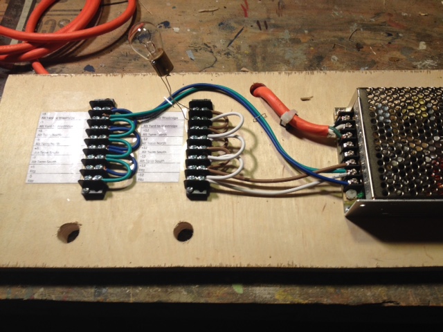 |
T Splicing Wire
3-23-2016
On most DCC layouts, feeders wires are attached to bus wires using
some kind of T splice. One of the things I am unhappy about on the
A&BR1 is my soldered T splices. Sure, they are strong and
they work fine, but they are pretty ratty looking. So in my
continuing effort to
make the wiring on the A&BR2 as neat and as bullet proof as
possible, I decided to look into the subject of T splices,
because I'll be making a hell of a lot of them.
I first considered using so-called suitcase connectors, but I decided
against this because they are designed to join two pieces of wire that
are similar in size, and on the A&BR2 I will be joining 12agw to
both 16 agw and 20agw, and 16agw to 20 agw. There is a lot of
controversy regarding the reliability of these connectors, and those
who claim to get reliable performance all say that one must stay
within the specifications of the connector to get good results. As far
as I can tell they can not accommodate wires of vastly different
gauges. So they are not an option, and I would rather solder anyway,
that is if I can learn to make a neater job of it.
As it turns out, there are two problems with T joints on the
A&BR1. First, the bus wires follow the track around under the
bench, which makes for a bit of a tangle, and often renders the T joint
difficult to access and create. On the A&BR2, the use of the bus
wire mounting boards will insure that all of the bus wires are laid out
in a neat rows, and all the the T joints are easy to access. Second, my
soldering ttechnique was not the best. I did
some
research about how make good T splices, and indeed, I found that I had
a lot
to
learn. I am using all strained wire and the reccomended method for
joining stranded is a little different that the method for joining
solid wire.
Here is what I learned:
1. Removing the insulation in the middle of a bus wire can be tricky,
and one must take care not to cut the wire itself, so a little practice
on some scraps is a good idea. I use my wire strippers, but for this
kind of stripping, I have learned to use the notch 1 higher than the
gauge I am scoring. If I am scoring 12 agw, I use the the 10agw notch
on the stripping tool. This will not cut all the way through the
insulation, but it
will insure that you don't cut the copper wire. Then I use a box
knife to cut a slice out of the notched area all the way down to the
copper. I then do a little more cutting with the box knife and a little
pulling
with a pair on needle nose pliers will bring the insulation cleanly
away along the score cut. For feeder-to-bus joints I strip a 1/2 inch
section the bus wire, and then I strip the end on the feeder to expose
3/4 inch of wire.
2. I then tightly wind the bare end of the feeder around the exposed
bus wire all the way up to the feeder insulation - about four turns.
3. I then paint the joint with flux paste, and using rosin core
electrical solder (not acid core) and a good sized soldering iron, I
heat the top of the joint well, holding the iron down on the joint
tightly for 5 or even 10 seconds. When the wire is good and hot, I
lightly touch the end of the solder to the place where the iron tip
meets the copper wire, and I slowly feed the solder down into the the
strands. Moving up and down the joint, I feed solder into to all the
turns. It is done when the entire joint is lightly covered in a very
thin coat of solder. It should be shinny, and the detail of the wire
strands should still be visible through the solder. This takes
a pretty good bit of solder, but be careful not to use too much.
You want enough to get well down into the joint so you don't have to do
both sides if you don't want to, but if you create globs of excess
solder, it can increase
electrical resistance in the joint.
 |
4. Finally, I have devised a way to tape the joint with a small piece
of electricians tape notched with scissors so it will wrap both joined
wires. You can figure it out.
This may all seem a bit anal, but this is the kind of detail that
separates the great model railroads for the good ones. Figuring out
and practicing details like this ahead of time will save much time
and
heartache later
and result in a much better installation. I am particularly looking
forward to using these techniques, because the linear bus wire mounting
boards will allow me to make all the T joints on bus wires mounted
right in front of me on the well-lit board, and not
hanging over my head in the dark under the bench.
Signals and Signal Placement
3-24-2016
Today, I have again been thinking about signals and signal placement.
There
are a lot of
of
ways to approach this, and a purist/prototypical approach is, in my
opinion, not always best. For one thing, it difficult to define
what is prototypical when so many rail systems in the US and worldwide
use any so many different signal protocols and varried sets of
operating
rules. On a DCC model railroad, as on many real railroads, block
occupancy and turnout
position are generally the keys.
In this regard, signal placement is of foremost importance, and it is
necessary to first devise a complete protocol and a full set of
operating rules in
order to place and program signals in a way that consistently indicates
the status of the track ahead.
I am
generally pretty happy with the set up I have on the A&BR1. I use
Digitrax SE8c
cards to control 3 aspect, double headed signal masts. I can control 16
masts (32 - red/yellow/green
heads)
with one SE8c card. Signal programming in TC can be
complex, but both the wiring and the installation of the masts is very
straightforward
thanks to Digitrax's use of 10 conductor ribbon cables between the SE8c
outputs and the individual masts.
In general, the system protocol I use on the A&BR1 and will
continue to use on the A&BR2 is this:
1. The upper signal head on each double headed mast is for the main
line; the lower head is for the diverging route.
2. If the diverging route goes off to the right the signal will be
placed on the right of the mainline track; if the diverginh route is on
the left, the signal will be place to the left of the mainline.
3. Red means either the bock ahead is occupied and or a turnout between
the signal and the next block is thrown in a way that will
derail the train.
4. Yellow means the next block is free but the block beyond that it is
occupied and/or a turnout after the next block but before the
subsequent block is thrown in a way that will derail the train.
5. Green means both of the next two blocks are free and all
turnouts before the second block are in safe pass-though positions.
6. Other than the dwarf signals, which reflect trunout position only, I
will not use signals in yards, so these rules apply only to main lines.
So with a double tracked mainline, like the one of on the A&BR2,
signals will generally be placed just after the stop marker at the
end of a block in
the direction of travel only.
In certain cases, where
there are crossover tracks, there will be signals on a single
track in both directions. If there are a lot of turun outs or
crossovers in the route ahead before the next block or in the route
beyond the next block, this can get a little hairy to program,
but programmmed, it all works nicely with TrainController. If the stop
markers are set near the end of a block as they
generally are, one can observe a train on a automated schedule
stopping to observe a red signal, and then continuing on under yellow
when the block ahead clears. To get this all right, signal placement is
key. One of the best tools for visualizing where to place signal masts
is the TrainController switchboard. This simplified, stylized, linear
block and turnout diagram makes it easy assess all the posibilities of
signal placement, traffic flow, block occupancy, and turnout position
in any given section of the layout. Here is the Fitzhugh section with
signal icons in place:
 |
I
prefer to place and wire and program all signals when I lay track. As I
go along
laying and wiring track and turnouts in a given section of the layout,
I also wire up all associated
dwarf signals and signal masts in that section. I addition, I program
the section's DS64s, and as I
progress, I create contacts in TrainController, enter all the installed
block and turnout
addresses, and
set up the block and turnout properties. I also set
the installed block max and min speeds, create the appropriate speed,
stop,
and brake markers, program station stops, and program the signal heads.
I then
preform rigorous testing including the running of trains on schedules
arond the section under construction.
It is easier for me to do all this block by block and turnout by
turnout, section by section as I go along - while I am focused on the
workings a single block or turnout or section.
A&BR2 Specifications
4-2-2016
Elsewhere on this web site I have posted the complete specifications
for the A&BR1. I am now far enough along with the planning of the
A&BR2 to post a similar spec sheet for the new layout.
Altamont and Blue Ridge Railway2 - Layout,
Power, and Control Specifications
Layout
Number of Power Districts - 5
Number of Power Blocks - 80
Number of Switches – 86
Track - Atlas Code 55 flex
Switches – Atlas Code 55
Switch machines – Tortoise
Turntable - Walthers 130' with DDC
Max Radius – 28”
Max grade – 2.1%
Bench Height 44.5""
Depth 34"
Room Corner Radii 48"
Wiring
Track Power Bus Wiring – 12AG
stranded, insulated, max 25’
Track Power Feeders – 16AG
stranded, insulated, max 3’
Track Power Dropper – 20AG tinned
bus wire, max 4”
Control
Computer – (2) HP –4G ram,
2.6Ghz, Windows 10
Interface –RR Circuits Loco Buffer
USB
Train Control Software – Fieiwald
Software - Traincontroller Gold F8/5
Power – Digitrax – CS100 DCC
Control Station and Booster, 5 amps
Power Management – (2)
Digitrax – PS42 Quad Power Managers
Block Detection – (5) Digitrax BDL168 Loconet
Occupancy Detectors and 1 BD4 Occupancy Detector (for separate
streetcar line)
Signal Control – (3) Digitrax SE8C
Signal Decoders
Stationary Decoders – (22)
Digitrax - DS 64 Quad Stationary Decoders
Mobile Decoders – Digitrax, TCS,
and Lenz - various
Sound
Control Software - Freiwald Software
4DSound (2)
Computer Playback - (2)- ENCORE
ENMAB-8CM 7.1 Channel USB Audio Box
Speakers
– (10) Gear Head Sp2600acb Powered 2.0 Desktop
Lighting
Dimible Warm Daylight T8 Fluorescents (19) USB Servo Controled
HUE Controled Color Lights (20) Wifi Controled
Custom Windows Software
TrainController
Gold
4-10-2016
I finally purchased TrainController Gold, and I have spent the last
couple of weeks getting the A&BR1 running under the new software.
The initial installation and switch-over to the new Gold F8 software
was actually remarkably easy. All of my settings came up fine, and
everything worked just as it had under TC Silver F7. However, as it
turns out, the upgrade for F7 to F8 involved changes to the way
the system calibrates Digitrax decoders, and so I had to re-profile all
my locos. This was over-due to be done anyway, so no complaints. Still,
it took quite a lot of time. After the profiling, I had to tweak some
stop markers, but in the end, I got it all done, and I was then able to
export all my loco train settings, including the new profiles, and
import them into the new TrainController Gold files that will be used
with the A&BR2.
Servo Controlled Dimmer for Train Room
Fluorescent Lights
4-11-2016
Back in December, I posted an entry to this blog detailing plans for an
improved train room lighting dimmer control system. Since I have no way
to electronically control the 600 watt Lutron dimmer I use for the main
train room lights, I have had to control things mechanically. The
current system on the A&BR1 uses a program loaded into an Arduino
microprocessor to send commands to servos that mechanically move
the dimmer sliders. The program is triggered from TrainController via
inputs from DS64 stationary decoders. This works fine, but it is a bit
cumbersome. The proposed new system will employ a servo control card
(SSC32) that will send servo addresses directly via USB from custom C#
desktop programs, which can be called from TrainController. This is a
much cleaner approach as it takes the Arduino and the DS64s out of the
loop. Below is a my design for the mechanics of this system.
 |
Yesterday I built this little module, using a lever on a
block-mounted servo attached to an 8 inch 2-56 steel rod
with a plastic ball link on one end and a plastic clevis on the other
end. I hooked the servo up to the SSC32, fired up the computer, and
with a few alterations, it all worked fine. The alterations involved
the spring steel rod, which I had included in the design in order
to apply tension to the slider and allow a little play with regard
to servo settings. Unfortunately this arrangement tended to twist the
tiny dimmer slider causing it bind. I ended up with the clevis directly
below the slider attached to the slider with a small piece of wire.
With this configuration, the clevis pushes the slider straight up and
pulls it straight down. This works fine, but it requires rather exact
servo-rotation commands, which were no real problem. I set the servo to
the center position and mounted the device board so the dimmer was in
the center position as well. I then used a calibration program I wrote
to try various rotation commands until I got an all-the-way-up and an
all-the-way down command that took the slider to the very end of its
throw just as the servo cut off. Below is a photo of the completed
installation. Now all of my lighting (both the fluorescents and the HUE
bulbs) is controlled by custom desktop C# programs that can be called
from TrainController.
 |
Servo with lever, rod, and clevis
attached to dimmer slider & the SSC32 Servo Control Board |
Programming the Lights on the A&BR
4/14/2016
I have made numerous references in this blog to the custom C# programs
I am using to control both the fluorescent and the HUE lights on the
A&BR. Now that the complete new lighting scheme is fully
implemented on the A&BR1 and it is acting as a prototype for the
future A&BR2, I will discuss these C# programs in overview. To do
this, I'll take as an example the Sunrise program.
Like all my lighting control programs, this is a Windows Forms
Application written iC# n
using
the Microsoft Visual Studio 2013. In
addition to the usual Windows Forms system references, this program
also employs System.Threading and System.Threading.Tasks in order to
support the
use of Thread.Sleep() program pauses. It also uses System.IO and
System.IO.Ports to
set up and communicate via the serial port, and Q42.HueApi and
Q42.HueApi.Interfaces (downloaded and installed using the NuGet
manager) to set up and communicate via WIFI with the HUE bridge.
using System;
using System.Collections.Generic;
using System.ComponentModel;
using System.Data;
using System.Drawing;
using System.Linq;
using System.Text;
using System.Threading;
using System.Threading.Tasks;
using System.Windows.Forms;
using Q42.HueApi;
using Q42.HueApi.Interfaces;
using System.Net;
namespace Sunrise1
{
public partial class Form1 : Form
{
public Form1()
{
InitializeComponent();
}
I next created a string to hold the private ip address of the
bridge,
which changes from time to time so I will get it each time I load the
Form. Since getting information
from the HUE bridge requires an "await", it is necessary to use an
asynchronous Form Load like this:
string ip;
private async void
Form1_Load(object sender, EventArgs e)
{
IBridgeLocator locator = new HttpBridgeLocator();
IEnumerable<string> bridgeIPs = await
locator.LocateBridgesAsync(TimeSpan.FromSeconds(5));
ip = bridgeIPs.ElementAt(0);
SunRise1();
}
The form
loads but is not visible on the screen, since I have changed
the Windows State property from "Normal" to "Minimize."
Now that I have the HUE bridge's current private ip address, I can
begin my Sunrise() sequence by connecting to the bridge using my user
name. This is a long character string that I got from the bridge using
the little debug application on the Phillips HUE site. Unlike the
private ip address, it does not change unless the bridge is reset, so
here I just perminently plug it in programmatically instead of
having the program get the information from the bridge each time at
start up.
private void SunRise1()
{
//initialize connection to HUE bridge
ILocalHueClient client = new LocalHueClient(ip);
client.Initialize("69a62616603b61014ec87aca2c4c0658");
Next, I set up a
new light command,
var command = new LightCommand();
Now I am ready
to manipulate the lights. For my sunrise, I first turned on the lights
at the lowest level of brightness and set the color to a nighttime
deep-blue. There are several ways to specify color in Q42.HueApi.
They all appear pretty cumbersome to me. I have elected to use Hex
pairs. The Color below, 6F1BFF,
represents three two place, HEX numbers, 6F, 1B, and FF, that is, the
RGB for the deep-blue I selected 111, 27, 255. Jesus!
////All lights ON/Dim
command.Brightness = 0;
client.SendCommandAsync(command);
//All Lights ON/blue
command.TurnOn().SetColor("6F1BFF");
client.SendCommandAsync(command);
Next I slowly turned up the
brightness to a little over 1/3 intensity (90 out of a possible 255) in
order to create a growing pre-dawn blueish glow (9 steps, lasting 1
second each). Notice that the Brightness function requires a
conversion to an 8 bit integer.
//Fade Up to 90
for (int i = 0; i < 90; i += 10)
{
command.Brightness = Convert.ToByte(i);
client.SendCommandAsync(command);
Thread.Sleep(1000);
}
I then slowly morphed the color from my deep-blue to the deep
red/orange that I will use for the sunrise (10 steps - 2 seconds each).
I have not devised a way to change color through the spectrum using a
loop, so I selected the colors I want for each incremental step and
coded in the sequence manually. (Note: I finally spent a little time
investigating the programming of colors using RGB and another
system that HUE uses involving xy coordinates to generate color. See my
post of 12-7-2016.)
//morph color from blue to red-orange
//bue/violet
command.SetColor("9D1BFF");
Thread.Sleep(2000);
client.SendCommandAsync(command);
command.SetColor("C31BFF");
Thread.Sleep(2000);
client.SendCommandAsync(command);
command.SetColor("E91BD2");
Thread.Sleep(2000);
client.SendCommandAsync(command);
etc. to
//red/orqange
command.SetColor("FF1B00");
Thread.Sleep(2000);
client.SendCommandAsync(command);
and then slowly increamented the brightness to full intensity.
//Fade Up to max
for (int i = 90; i < 255; i += 13)
{
command.Brightness = Convert.ToByte(i);
client.SendCommandAsync(command);
Thread.Sleep(1000);
}
Then I morphed the color slowly from the deep red/orange to a warm
white daylight, (in the HUE system, some colors are much brighter than
others, so in this case, slowly changing the color from deep red/orange
to a warm white, also causes the entire scene to slowly get brighter)
//morph color from hot red-orange to warm redish white - 8 moves ~ 16
sec
command.SetColor("F61E00");
client.SendCommandAsync(command);
Thread.Sleep(2000);
etc. to
//warm white
command.SetColor("F68B7B");
client.SendCommandAsync(command);
Thread.Sleep(2000);
Next, I
used SSC32 protocol (servo
= #1,
rotation = 1720 microseconds, duration = 15 seconds) to send a serial
string to the servo telling it to slowly fade up the fluorescents
to full daylight over a period of 15 seconds. Servo rotation
is controlled by sending a PWM signal along the servo's control
wire. In this case, I sent a pulse width, "P," of 1720 microseconds to
servo #1, which will rotate the servo a bit beyond the center to my
"all-the-way -up" position." Most servos have a 180 degree throw
with 1500 being the center at 90 degrees, 500 being zero degrees and
2500 being 180 degrees. It is generally recommended to work between 750
and 2250 and avoid sending the servo to the limit of its throw. In this
protocol, the speed of the servo move is specified by "T," the number
of milliseconds for the entire move. In this case I have specified
15000 milliseconds (15 seconds).
String codeString = ("#1 P1720
T15000 \r");
SerialPort serialPort1 = new SerialPort("COM3", 115200, Parity.None, 8,
StopBits.One);
serialPort1.Open();
serialPort1.Write(codeString);
serialPort1.Close();
Once the powerful warm day light fluorescents are at full
brightness, the HUE lights
become surperfluous and can be slowly faded out and then turned off,
and
the program can be programatically terminated.
//Wait for fluorescent room lights to fade up to full
Thread.Sleep(20000)
//Fade Down to
Min ~ max speed ~16 sec for 8 moves
for (int i = 255; i > -1; i -= 30)
{
command.Brightness = Convert.ToByte(i);
client.SendCommandAsync(command);
Thread.Sleep(1000);
}
//Reset all Lights to
Red-Orange and then turn off the HUE lights and close the program
command.TurnOn().SetColor("F61E00");
client.SendCommandAsync(command);
Thread.Sleep(1000);
command.TurnOff();
client.SendCommandAsync(command);
Thread.Sleep(2000);
Application.Exit();
Layout
structure lights and street lights etc. are controlled by using
Traincontroller to address a DS64 stationary decoder.The polarity
reversing characteristic of the DS64 output is conversed to a current
ON/OFF circuit using a zenor diode. The DS64 output can
then operate a relay to turn layout lights on and off. The DS64 layout
lights off command is in the same operation window as the execution of
Sunrise program, but the layout-lights-off operation is timer-delayed
until after the sunrise program has closed using an operations
delay set in that window in Traincontroler.
Some File Management Housekeeping for
TrainController
4/23/2016
As mentioned in an earlier post, the conversion from TC Silver F7 to
Gold F8 went well. It did however point out some errors in my file
structure. TrainController, I have come to find, is designed to
operate with all associated files in a specified default directory
that it creates under C:\\Users\\UserName\\Documents. One can, of
course, place files where ever one wishes as long as one updates
the links to these files in TC. I had placed all of my TC-associated
sound files in a separate directory, and it was not until I
installed TC Gold and imported my Engnes and Trains data that I found
out that a new TC file would
not automatically connect to these files. I did not think much of this
at
the time, I just updated the unsuccessful links (paths) in TC Gold and
went on with a successful installation.
During this time I had also been fooling around with Microsoft
OneDrive, at first syncing some WORD files to a backup in the cloud in
order to have an ongoing, constantly undated backup. This involved
placing the WORD file in the OneDrive folder, selecting it as a file to
be synced to the cloud, and then working with that file in the OneDrive
folder. This worked great, so I reasoned, why not place all the files I
manipulate on a regular basis, like Quicken, Outlook, TrainController
etc., in the OneDrive folder, work on them there, and sync them to
the cloud so they update a cloud-backup with each change. I tried it
with Quicken and it worked fine. But with TC the inability to
automatically find the paths to files not in the default directory
looked like a problem. It ran fine in the OneDrive folder and backed up
fine, but moving it away from the default folder meant I would have to
update the links every time I updated it back.
Well, I reasoned, I'll leave it in the TC default folder, work on it
from there, and write a little C# program using System.IO to copy it to
the One drive folder automatically each time I close it. Some thing
like this:
string
sourcePath = @"C:\Users\Wilber\Documents\Railroad &
Co\TrainController";
string
targetPath = @"C:\Users\Wilber\OneDrive\TC";
{
Directory.CreateDirectory(targetPath);
}
foreach
(var srcPath in Directory.GetFiles(sourcePath))
{
File.Copy(srcPath, srcPath.Replace(sourcePath, targetPath), true);
}
Application.Exit();
}
This worked fine for moving things around and over-writing
files to any folder except the
OneDrive folder. It turns out that the OneDrive folder can only be
accessed by direct user action, and will not accept automated commands.
While I was researching this, I found that it is NOT recommended
to use the OneDrive folder to sync Quicken or Outlook or other my
other large
files that are written to while running. These
kinds of applications create just too much activity, and one runs the
risk of data loss, file corruption, or worse. So it was back to the
drawing board.
The good news is, I learned a lot. I now upload backups to the
cloud for all my high-use, currently active files often (at least
weekly), and then I do my monthly back up of all non-system files to my
Seagate 1TB external hard drive as usual. In the process I have
returned all TC-related files for both the A&BR1 and the A&BR2
to the default directory and updated all links, I hope for the last
time. Whew!
May 2016
Troubleshooting Loconet After a Lightning
Hit
5-7-2016
I live on the top of a
mountain in North Georgia, and lightning is an ongoing problem. I have
taken three hits that rendered the A&BR1 inoperable since it
was begun back in 2008, so I am getting pretty good at troubleshooting
when my entire system goes down after after a hit. Here is how I
go about finding the problem(s).
Generally, if lightning causes damage to any component on a loconet
network, that component will corrupt the network signal and render the
entire system inoperable. It is pretty easy to find the faulty
component if there is just one component damaged. It gets a little
trickier if there are several damaged components. On
my Digitrax system, if a component is corrupting
loconet, I get an error message in the form of nine audible
beeps.
As a first step, if you have a computer connected to loconet via a USB
interface, unplug the interface and try the system again. I use an RR
Circuits device as a USB interface. To my mind, this is the best
loconet/USB interface, but it is very susceptible to lightning damage.
(The newer units are quite bit more robust in this regard than the
older ones.) If the system works after you disconnect the USB
interface, replace the interface and you're done. If not, leave the USB
interface unplugged, for it may very well still be bad.
Next, completely unplug loconet from the booster. The first piece of
information you want to know is is the booster working, so plug a
throttle directly into the booster and check to see if you get track
power, then see if you can run a loco from the throttle. If so, you
know the booster and the throttle are good. If not, try another
throttle, or check your throttle on a spare booster if your have one.
If the booster is inoperable
from a know-good throttle and you can't get track power or run a
know-good loco, the
booster must be repaired before any further troubleshooting can be done.
Next start plugging in
the remaining devices in
the loco net chains(s). Work one chain at a time, and either
unplug devices one at a time working back in from the end of a chain to
the booster, testing the system as you go , or go out half way out
and disconnect half the devices in groups until you find the culprit.
If
there is only one device in the chain that is bad, you will find it
pretty easily this way. If
there are several, it might be best to use a long
loconet cable and check each device individually to see if it corrupts
the booster or not. As
you find the damaged device(s) using either method, take it (them)
out (bypass) of the chain, and plug any other chains back in and
test the system. If it works. go to the last step. If not, troubleshot
he next loconet chain using the same method.
As a last step, once you have found all the bad devices and the system
is functioning, plug the USB interface back in to test it.
Lightning is strange stuff. It often selectively takes out only a
few compontents in a chain of many. So far, lightning damage on the
A&BR1 has been limited to the USB
interface unit, signal control cards, and once an occupancy sensor. I
have never had more than two devicces wiped out at once by lightning, I
have not
experienced a booster failure due to lightening, nor have I had any
kind of lightening-related decoder failures, although I suspose these
are possible.
DPM Kits
5-10-2016
We've had delays starting the new building owing to technicalities with
the building permit, County Land Use Board etc. Don't ask! We should
break ground soon. So the new train room is still at least 6 months
away, and I have done pretty much all the planning I can do. So what's
next? Well, I'm going to need a lot more structures, so I guess I'll
start building kits.
Anyone who models early to mid 20th century N scale towns and
cities should be familiar with DPM (Design Preservation Models) kits.
DPM makes a line of simple, nicely detailed kits that generally
fall in
three categories. Brick stores and shops, brick low to mid-rise
commercial buildings, and small to medium brick warehouses and
factories. Typifying small town structures built in the first half of
the 20th century all
across America, these
kits are easy to build, relatively inexpensive and very versatile. They
form the backbone of the town architecture on the A&BR1 where I
have
scores of them, and they will do the same on the A&BR2 where I'll
need scores more before I am done.

|
DPM Structures on the
A&BR1 |
I decided to begin by building, assembly line style, 16 small DPM
stores and shops, so I ordered 16 kits (2 each of 6 different kits, and
4 kits of another design that I plan to kitbash into a single large-ish
building) - all at a cost of about $220. What follows is a step by step
account of the mass construction of the 12 kits to create and
detail 12 very different structures from 6 different kit designs. I'll
deal with the kit bash of the remaining four structures in the next
post. There
are many ways to go about this, and there is nothing magical about my
approach. It is just the way I do it.

|
The kits |
Organization:
Working on 12 very similar kits at once requires some organizational
discipline
to avoid getting the parts and pieces mixed up. So I begin by
getting a large board with 16 small open containers on it. I then open
all
the kits one at a time and
wash the wall sections in warm soapy water to remove any oils leftover
from the manufacturing molds. I then
rinse and dry the sections and I place all the contents of each kit
along with
the kit
label in a container. I then go back and, one kit at a time, cut the
residual plastic sprue material from the wall sections and trim and
sand the edges, returning each wall sections to its container as
I go. As I paint, assemble, and detail, each structure,
I
will always return it and any associated parts to its container so it
does not get mixed up with any
other
kits. This is very important, because the components of all of these
kits look very much the same.

|
The containers
|
Painting:
Paint It Black
The first thing I do is paint the inside of all wall sections
black. Working in carefully laid out groups of 4 kits, I lay
out
the wall sections on my painting board and spray a coat of flat black
straight down on the the insides of the wall sections to ensure that
they will be completely opaque when they are lit
from within. I then return the 4 sets of wall sections to their
respective boxes and go on the the next set of 4. This goes very
quickly.

|
Painting the inside of the
wall
sections black. |
Color Schemes
The next thing I do is to plan
my color schemes - 1) the color of the brick, 2) the color of the
window
trim, and 3) the color of the other wood and masonry trim for each
structure.
I
place a small label on each box to indicate the color scheme for each
structure. Of the 16 little stores and shops, 8 will be unpainted brick
(4 each in two different red-brown shades), 4 will be brick painted a
medium gray, two will be brick painted ocre, one a cream color, and one
will be brick
painted white. I'll use 6 different colors for the window trim (white,
black, light gray, dark gray, dark brown, and dark green.) Some of the
bare
brick structures will get
a light colored wash to articulate the masonry between the bricks. The
some of buildings will only get a dark, weathering
wash, some very dark and dirty, some not so much.
All of the window trim colors will be sprayed on first using
regular canned spray paint (see below). Then after masking the window
trim, I'll spray on the brick colors.
I'll use 5 different colors for the wood and masonry trim (white,
black, light gray, dark gray, dark green, and light green).
They will be
sprayed on or brushed on using acrylic model paint (see below).
Spray Paint
I don't generally use an airbrush. Although one can do
amazing things with these tools, they are just too much trouble for me
in most
cases, and when it comes to painting structures I can get
excellent results using regular
canned spray paint and a myriad of non-airbrush weathering techniques.
For plastic structures flat spray-on colors are best. I have had
excellent results using primer, which, generally comes in three
different very useful, very flat colors: red/brown, medium gray, and
white. Also the spray-on camoflauge colors that are now available are
excellent and very flat (dusty greens, tans, browns, and grays). But
any
old flat spray paint works. (If you need a color that you can't find in
a flat finish, then you can use a satin finish or even a gloss, and
then over paint with Testors Dull Coat.) Apply your spray paint
from about a foot away using slow, steady, even swipes from
different angles. Do not stop
moving, and do not over-paint. Spray lightly, just enough to get
complete coverage.
This stuff is very thin, so the paint tends to quickly get in all the
cracks allowing all the detail to show through. The coverage is
excellent, and it dries very quickly. Since these spray paints are not
water soluble, they have the advantage of tending the hold fast when
you later use water or alcohol-based washes or rubs to weather or to
articulate
the masonry in the brickwork.

|
I keep a variety of
canned flat
spray
paints,
primers, and camouflage colors on the shelf in my shop. On hand I
generally have: black, white, dark
green, olive green, light yellowish green, yellow, dark gray,
medium
gray, light gray, light tan, cream, medium tan, dark brown, 2
shades of brick,
light blue, light pinkish purple, as well as metallic aluminum, several
gloss coats, a
matte finish,
and Testors Dull Coat. |
Brush-on Paint
For years I used Testors Poly-Scale Railroad Colors, but they
discontinued that line, and so I went to Testors
Model Master acrylics. These give very good results if the consistency
is just right, but they tend to thicken up after opening, and they are
not completely water-soluble (you can clean up with sap and water, but
you shouldn't try to thin these paints with water). Recently I've read
a
little about the
water-soluble Vallejo acrylics from Spain, and so for this project, I
decided to
try them. They available in 100s of colors, and sets are available in a
large variety of color mixes. The
sets designed for painting plastic replicas of tanks and armor seem
to fit the bill (nice, soft, grays and greens and tans and browns.) A
number of my Model Master colors are dried up or about to go South, so
I ordered a set of 16 WWII armor colors from Amazon at cost of about
$45. We'll see.

|
My Paint Box with the
new
Vallajo WWII Armor Assortment in the lid. |
Painting the Wall Sections
Not too long ago, in
order save the tedium of hand painting the window trim,
I devised a technique that involved spraying on the window trim
color first,
then masking each window, and then over-painting with the final brick
color. For
years I did this by hand, thinking that it was not possible to
successfully mask these tiny windows. But using careful application of
regular canned spray paint over tiny window masks cut-in-place
using matte finish Scotch
Brand "Magic"TM Tape cut with a very sharp hobby
knife and lightly tamped down into place with small stick of balsa,
yields much better results than the results I got painting the trim by
hand, and it can be done in a
fraction of the time.

|
Again working in groups of
four, I
first spray paint the brick side of all the wall sections
using the window
trim color. Here the window trim will be a nice dark-chocolate brown. I
do not spray straight down, but rather from angles
to insure that inside of the window frames are covered. Four quick
light passes, spraying at angles first from 12 o'clock, next from
3, 6, and finally from 9 o'clock ought to do it. I
then let them dry completely. |

|
Cutting the mask for the
individual
windows is a bit tedious to be sure, but it goes
surprisingly fast once
you get the hang of it. The secret here is and very sharp hobby knife
and the very thin, not too
sticky, Scotch Brand tape used for the masking. It is easy to cut,
it stays in place, is easy to remove almost immediately after
painting, and it does not bring any of the window trim color away with
it. In cases where the window trim is to be the same color as the other
trim, you can mask off the store front and the top cornice as well
before painting the brick. |
 |
Over-paint the brick wall
color. Here I've used a mustardy ocre color from my new Vellajo paints,
which are great - good coverage, good consistency, good container. -
very nice. Again, if you use spray,
just enough to cover. Don't soak
it. When the paint is starting to
dry but
not fully dry, remove the window masks with tweezers. Then after
the overcoat is completely dry, touch up with a brush dipped in a tiny
bit of the trim color spray paint sprayed into a small cup. Generally,
not much touch up is needed, and generally the
line along the window trim is much cleaner than anything you could
paint by
hand.
|
 |
Next paint the other
trim,
including the storefront, and the stone window headers,
capstones,
and sills. This
is generally easy, owing to the fact that most of this is painting
raised surfaces, so nice, clean edges are easy to get. If the
store
front
is to be the same color as the window trim, you can simply mask it off
before you paint the brick. If it is a different color, you can spray
paint
it by masking off the brick, or you can hand do it. No big deal.
|
Paint-based Weathering and Dull Coat:
If you are using any
weathering techniques that involve paint, or
dry-brushed paint, go ahead and do that now.
 |
I generally use a thin
white acrylic paint wash to
articulate the masonry of unpainted brick. A few drops of acrylic white
mixed with maybe 1/2 tsp water and rubbing alcohol to break the
surface tension - about a 50/50
mixture. The idea is to get the wash to remain in
the recesses
of the
masonry joints. It is best to use a very light color for window trim if
you are going to use the masonry wash.
|
When any paint-based weathering is thoroughly dry,
apply any dry
transfers or decals using plenty
of setting and solvent solution to get the decals
well down into the texture of the brick. Let the decals dry for at
least a day. Then over-spray all
your painted wall sections (with or withour decales) with Dull Coat.
Further Weathering:
For weathering painted brick.
I use a light black wash of acrylic or
ink and sometimes I use pastels or chalks rubbed on by hand
to get dusty effects. I apply weathering washes and chalks
and pastel after I
spray with Dull Coat because Dull Coat or any matte or flat
lacquer spray will tend to dissolve the washes, chalks, and
weathering and greatly lessen their effect. This means you will
have to exercise care in handling these structures because some of the
weathering (especially the chalks and pastels) are not set, but getting
the
weathering effects right is a lot easier if you weather after the
Dull Coat is dry and not before your spray it.on.
When everything is completely
dry,
assemble the wall sections of each structure using a good square
to maintain perfect 90 degree angles while the glue dries. Add the roof
rails, spray paint
the roof flat black on top and leave the underside
(inside) white so it will reflect the directional 5mm LED bulb
that will illuminate the inside of the structure during night
scenes. If the kit comes with a roof that is not white styrene, spray
paint the underside
of the roof white, let it dry, and then spray paint the topside
flat black. After it is dry, install the roof and glue in place.
 |
If you are going to
have any
stacks or pipes coming up through the roof, drill holes, paint the
pipes
and glue them in place now. Also glue down any large roof-top
structures. After everything is dry,
paint the flat
black roof top with a rather thick coat of white glue, and
sprinkle on some ballast. I like to use regular gray or multicolored
HO ballast. I like the look of it better than N scale ballast
which is just too fine for my tastes. I will also often sprinkle on a
spot or two of black or dark gray ballast or brown or tan to keep
things from
looking too pristine and perfect. I also sometimes leave the black
roof top showing through or partly showing through in a few spots,
and I sometimes add dabs of black acrylic paint to simulate
tar spots or patches etc. Unless you plan some really large roof
top structure, you can glue smaller details like pipes and vents, and
tanks over the ballast. |
Now you can add all sorts of details:
the doors, if separate, smoke, colored awnings, downspouts, pipes,
vents, water tanks, little
shed roofs and porchs, ivy, or other climbing vines - whatever you can
imagine. I keep a little box of rooftop details salvaged from other
kits, pieces of sprues, and many other sources. For example, florist
wire is very handy for making rooftop pipes and down-spouts etc. or a
tiny round-headed screws with the slot puttied-in and painted silver or
black or rust color makes a cool vent dome. You will be surprised how
much you can find, if you just keep your eyes open. Remember, since you
look down on the layout, you see more rooftop than anything else, so
rooftop detail is very important in achieving interest,
variety, and realism.
Finally, I glue in the window glass and affix any window decals, dry
transfers or signs. I
like
to black out a few windows using electricians tape, put a few shades
down or in the half-down position using tan translucent masking tape,
and occasionally I remove the mulls and board up a few windows here and
there using
flooring scraps from etched wooden kits. And last of all, I place an
LED inside the structure, turn out the lights, and check for any cracks
along the roof and wall seams where light might shine through. I patch
these from the inside with putty or with black electrical tape. Et
Voila!
 |
A DPM Kit Bash
5-24-2016
Kit bashing is an art, and it can really get elaborate. I generally
don't get too carried away with kitbashing, although I do it quite
often. Generally I kitbash structures to make them fit into a specific
space, or conform to specific elevations dictated by the terrain.
DPM kits lend
themselves well to this, and the company even sells modular factory
wall sections of various descriptions designed especially helping
kitbashers expand, modify, and marry various kits.
 |
Here is a large
milling factory on the A&BR1. This complex, designed
to fit
terracing in a steep hillside, was kitbashed from
several DPM kits and a handful of extra wall sections. |
Also I often use kitbashs to create so-called "background"
buildings,
or "backdrop buildings,"or "half buildings" - shallow structures
usually placed against or near the backdrop, that
give the illusion of
depth but
actually are only about 1/2 inch or so deep. (See my tutorial "Marrying
the
Layout to the Backdrop" for informtion about this and other forced
perspective techniques.)
 |
A "Background"
Building. Each DPM kit will, of course, yield two of these: a
front
section and a rear section. |
One of the shortcomings of the DPM line is that all of the shops are
multi-story structures, and although most small towns contain lots of
multi-story buildings, they also generally contains lots of one-story
buildings. So
I often kitbash to make a few lower buildings to give variety to a town
street.
Here, I am kitbashing 4 identical DPM three-story kits to make one
large 4-bay
building with two one-story bays in the center section and a
five-story "U" shaped high-rise surrounding three sides of the low roof
top. Below is a photo of one of the
four identical kits used, and a "work in progress" picture of the
kitbashed
structure taking shape on the bench.
 |
Completed DPM kitbash. I have only to
add the shop signs on the four latteral sign hanging shafts above the
doors and place a small water tank to the roof, and I'll be done. |
I plan to place this building on a city street, deep in the layout,
in a place where the back of the building will not be visible to
viewers, so I will just use plain
styrene for the back and get the bonus of having the three
surplus first story rear wall sections (I used one for the rooftop
service structure) to use in making some
additional
"backdrop buildings."
Windows 10 Problem vis a vis 7.1 Surround
Sound Box (ENCAB-8CM)
5-31-2016
Several months ago, about the same time I switched to TrainController
Gold on the A&BR1, I updated the trainroom computer to Windows 10.
Everything worked fine, but lately a problem has popped up
involving the ENCAB-8CN 7.1
USB Surround Sound Box. Somehow this unit got reset, and
it now appears to be suck in the stereo mode. Under Windows 10, I
cannot address it to reset it to the 7.1 Surround Sound mode because
the Encore Electronic Company that manufactured the box has gone out of
business, and so a Windows 10 Driver update is not available. The
original driver installed a control program and it all worked fine
under Windows XP. It works under
Windows 10, but the control program is not present under Windows
10. So I can't change the settings. Unless I can figure a
way to address this little box, I'll have to replace it. Not really a
big deal: It only cost about 30 bucks. My
girlfriend has an old Windows 7 laptop that
she no longer uses, so a may borrow that, load the old dirvers for the
ENCAB-8CN into to it, and see if I can reset the unit to 7.1 using
Windows
7. This might work, but how long this fix will hold, I cannot say.
I've got my eye on an inexpensive 7.1 Surround Sound System which
includes an amplifier/receiver, and 7 speakers for under $200. I
will probably buy this system for the A&BR2. The old ENCAB-8CM and
three of its small
speakers can then be used in stereo to power a left, center, and right
setup from the networked second computer that will display the
switchboard and control the long center section of the bench
supplying
discrete stereo sound to that section independent of the 7.1 Surround
Sound for the peripheral benchwork.
Update: 6-8-2016. I got the USB Surround box working again, by
installing the driver in an old laptop running Windows 7 and reseting
the software to 7.1 output. Then when I connected it to my Windows 10
laptop, I found the control program, not on the task bar as before up
on the control panel. Perhaps it had been there all along. Whatever the
case, it worked fine, although
TrainController sound dropped out several times before it stabilized
and began to function normally. The drop out appeared to be caused by a
faulty USB connection. It is working for now, but I suspect
there still may be a driver issue with Windows 10.
June 2016
Prototyping
Layout Lighting Distribution Blocks
6-1-2016
Note:
Since I later decided to not to use the 30 agw wraping wire, and switch
to a 20 agw daisy chian method, I will not use the distribution
blocks
detailed below. (See post of 6-24-2016.)
There is nothing on the layout more simple than the wiring for the LEDs
used to light structures. I plan to use a simple 5 volt, 6 amp
circuit bridged in parallel by a large number of 5mm LEDs each
attached
to
a 200 ohm resistor, and each drawing about 10ma of current. I
choose to wire in single-bulb, parallel circuits because I want to keep
all the connections on the wiring mounting board and not up under the
bench. This power distribution block will also send 5 volt power to
the Tortoise Interfaces to power the dwarf signals, in which case, the
resitors will be omiited since they are already installed in the
Tortoise
Interface. On the A&BR2, I will attach each LED leg
or Tortoise
Interface position to a blue and a green
30 agw feeder and then bring the feeders back
in neat bundles to the wire mounting board and along the
board to a Layout Lighting Distribution Board where I will attach
labels and resistors as needed, and connect each pair
to the + and -
power bus. This puts all connections and labeling (except those at the
LED itself or fro the tortoise interface to the LED)
in clear view and easy access on the distribution board. These parallel
runs will be on average about 2 to 3 feet long, and, given the low
current requirement of a single, 5mm LED, the 30 gauge wire will be
more
than adequate and will create minimal resistance. Also the expense
will
be minimal because the 30
gauge wire is really cheap, only few dollars for 1000 feet.
 |
Here is the prototype with its label
and with + and - 30 agw wires and resistors attached to a 24 pin strip,
enoungh for 12 LEDS.
Note:
Since I later decided to not to use the 30 agw wraping wire, and switch
to a 20 agw daisy chian method, I will not use the distribution
blocks
detailed here (See post of 6-24-2016.)
|
This prototye employs a long narrow custom made circuit board with
muliple posts. For the negative (green) wires, I have soldered a 30
gauge
feeder to each negative post on the top side of the board, with one end
of
a resistor (mounted on top of the circuit board) soldered to the
corresponding post on the bottom side of the board. The
other end of this resistor is soldered to the negative
power bus on top of the board. If
the connection is to a Tortoise Interface to
power dwarf signals, I omited the resistor and took bottom side post
straight
to the power bus, since the resistors are already installed in the
Tortoise Interface. For
the postive (blue)
wires, I have attached a 30 gauge feeder to the postive posts on the
top side of
the board and bussed the corresponding positive pins on the bottom
of
the
board to the positive power bus. So everything is right there in
front of me, connections to
LED feeders, power bus, labeling, and resistors. I did not wire one
side as a single looped-through common return for it
would have required larger wire, and a lot of
connections under the bench. The long individual 30 gauge
wires
don't
really cost anything to speak of, and the 30 gauge wrapping wire is
very easy to install in neat bundles.
I'll now go ahead and build five or six more of these 12 LED, 24 pin
boards. How many I will end up needing, I do not know. I have
more than 150 structures on the A&BR1 with probably about 200
individual bulbs. I'll likely need about two to three times that to
complete the
A&BR2, so maybe 400 to 500 LEDs (that is probably 4 or 5 amps
worth)
and maybe 30 or 40 Distribution boards in all. That is all a long
way
off right now. Last of all, I built a little test setup on a
breadboard using 4 - 5mm warm white LEDs powered from the prototype
distrubution board. I measured the
current draw of the circuit at about 39ma, about 10ma for each LED as
calculated.
(Note 6-20-2-16: When I began to install the dwarf signals on the
first prefabricated track module for the A&BR2, I found that
working with the 30 gauge wire was a real problem. It was just too fine
to effectively deal with. So in the end, I did away with it and with
the above described lighting distribution board in favor of a more
convention scheme using a green and blue 20 agw primary wire sub-bus
off the main 5 volt power bus to daisy chain to each tortoise
interface block and supply all the dwarf signals on the module.
I'll use a similar scheme to daisy chain to multiple LED lights for
structures. Labels will be affixed to the underside of the bench at the
tortoise interface or where the penetration is made for each LED. Also
a label listing all the LEDs supplied will be attached on the wire
mounting board where each 20 agw sub-bus attachs to the main 16
agw 5 volt lighting supply bus.)
Beginning to Lay Track - Perparing to Construct Prefabricated
Sections
6 -7-2016
At this point I am totally comfortable with my track plan, as
well as with the bench design, the new XCAD track plan renderings, the
TrainController Switchboards, the wiring labels, and the Turnout and
Block Lists I have created. With all of this well in hand, I can now
begin to lay track even before we break ground on the new train room.
Many of the most complex sections of the layout can be prefabricated on
plywood/homosote boards, designed to perfectly fit the future bench
work
and to still allow enough play for small "fitting" adjustments when
they
are married to the built-in-place sections of the layout. Laying track
and wiring is a lot easier on these prefabricated boards because it
is easy to light and access and does not
require crawling around under the bench work. I did several sections of
the A&BR1 like this using a specially fabricated work bench, and it
works
great if you follow these basic rules. Using this approach, I a get the
lions share of the track for the A&BR2 laid before building with
the new train room is completed.
Here are some
guidelines regarding prefabricating track sections:
1. Plan well. To prefabricate and then successfully install sections of
track, all of your planning has to be prefect. Measurements
of the track plan and the bench work design must be exact.
If you prefab sections, there will be little room for
modification to scheme
after you begin. For this reason, I do not recommend prefabrating track
sections to beginners.
XCAD is great for
this kind of planning and measurement verification, and after I
complete the overall track plan, I generally go back
and create a very detailed, separate XCAD file for each part of the
layout with special attention to the sections I wish to prefabricate. I
don't generally prefabricate a section that is on a grade, so
elevation detail is not often a construction issue here, but I
recommend that an elevation plan be in place and that all grades are
completely worked out in advance of any prefabriation. Pinpoint turnout
location accuracy is essential and special
attention should be
given to exact track spacing and to electrical continuity and all
electrical isolation requirements.
2. Select wisely. The choice of which sections you select to
prefabricate is critical. Generally, I choose flat
routes between longer blocks, especially if they contain multiple
turnouts. I also choose sections that connect to longer sections
of in-place
track at each end allowing me a just little slop to perfect the
connection of the
prefabricated track with the rest of the layout. It is best if all
the track ends in a prefab section marry
to a short section of straight track and then to an easement. This
means that, when I move the prefabricated sections around to get it
lined up, I can also make very fine adjustments to track sections
connecting to the prefabricated section without having to modify the
easements of the large radii that they lead to.
3. Take care in handling your prefab sections. I like to build a
special work
bench that is like a little section of the bench work - about 44 inches
high, 1 x4 open framed top - just like the bench work - 2 feet wide and
8
feet long with a cross member every two feet. This bench has its own
work light bar and it is outfitted with 5 volt and 12 volt
power buses, as well as with track power output from my spare
DCS100 and with loconet. With this set up I can fully test each
completed section using a DCC throttle to throw turnouts and run locos
and even short trains. I generally temporarily screw some kind of
wooden cross members above the track on the
top side of each section so that the section does not rest directly on
the track where I turn it over to work on the bottom side.
 |
Track Layoing Work Bench |
I have ordered two sheets of homosote, some 3/4" plywood, and the
2x4 and 1x4 lumber for my little work bench, as well as some cork
roadbed and an additional DCS 100. While I am waiting for delivery, I
can
get everything else ready.
I'll need:
homosote
3/4 " plywood
XCAD print out
turnout list
straight edge
cork road red
white glue
1/8" cork for pads
cork roadbed strips
turnout templates
3 RH #10 Atlas Code 55turnouts
3 LH #10 Atlas Code 55
turnouts
1 LH #10 Atlas Code 55 turnouts
Atlas code 55 flex track
dark brown, light brown, light gray, and white spray paint for
wreathing
turnouts and track
rust colored acrylic paint for painting rail heads
black marker for drawing the center oil stain.
soldering iron and solder.
22 agw uninsulated solid bus wire.
20 agw red, black, yellow, brown, and white wire
20 agw green and blue wire
7 tortoise switch machines
14 dwarf signals
Mounting screws for tortoises
wire ties
7 tortoise interfaces
printed labels
3/8 drill and bits for wires, tortoise rod and signal masks
 |
Ready to lay track, wire, install
tortoises on perfab section |
The plan is to weather and attach droppers to the turnouts, draw the
center
lines, fashion and mark the cork using
the turnout templates, drill
holes for wires, tortoise rods, dwarf
signals and regular signal
masts, drill holes for tortoise throw rods, glue
down cork, lay track,
install Tortoise machines, install
Tortoise interfaces, wire tortoise interfaces, droppers, and feeders,
label Tortoises, Tortoise interface, and feeder bundles, hook up and
wiring and perform checks. I'll just tack the track in place until I
get
this section in place attached on bench and married to the
in-place track. Then I'll tweak the alignment and glue it down using
Elmers white glue just as
I did the cork roadbed. (I use white glue here because it is less
permanent than other glues - should I need to pull up a section of
track or roadbed for any reason, I can just wet it down a little and it
will come right up nice and clean. In this regard, when I glue
down track, I generally do not put much glue on the turnouts - just a
small amount at each end- so if I need to pull a turnout up to make and
adjustment, it will come up easily.)
Weathering turnouts
6-8-2016
I have already weathered a number of sections of flex track (see
details of my track weathering technique in the post
of
1-19-2016), so I need only weather the 7 turnouts needed for the first
Fitzhugh prefab section. Again I use canned spray paint and a clean rag
to thoroughly wipe the rail-tops clean after each coat. First, several
passes using
a flat dark brown sprayed on at angles to insure the rail sides are
coated, then a dusting of medium gray and a dusting of light
tan all sprayed straight down on the turnout. Then I use a small bush
to paint the nail heads rust color.
 |
Here is a weathered turnout in the
foreground beside an
unwaethered turnout. |
Wiring Turnouts and Track
6-9-2016
As discussed in the post of 1-18-2016, I plan to use only three
droppers for each Atlas Code 55 turnout: one for the frog, and one each
for the left and right stock rails. I will trust the turnout's internal
connections to the closure rails, the pivot rails, and the exit rails
so no additional bonds will be added. I first cut away a small section
of the plastic tie material from the underside of the turnout to
expose the stock rails. Then,
taking care not to touch the plastic with
the hot iron and not to solder the stock rail to the guard rails, I put
a very small dab of solder on each exposed stock rail and a tiny drop
on the copper frog connection ring. I then solder a short piece of 22
agw pre-tinned bus wire to each of these three places. I then test the
strength of each solder joint by pulling rather firmly on the bus
wires. They should bond to the rails well enough to withstand a light
but firm tug, and you should be able to lightly bend the bus wire back
and
forth lightly without weakening the solder bond. Finally, I trim
the
bus wire droppers to about 3/4 of an inch and solder the three
colored
stranded 20 agw dropper extension wires in place - yellow for the frog,
and red
and black for the stock rails. For the red and black wires, which
side is red and which black depends on the orientation of the
switch. My general
rule is the the red wire is attached to
the rail adjacent to he outside edges of the bench, and the black wire
to the rail adjacent to the center of the bench. These
colored dropper extensions should be long enough to reach from the
turnout to the tortoise interface.
 |
Below is a turnout with the two small
sections of plastic sleeper material cut away beneath the stock
rails adjacent to the frog. (you can do this anywhere you like on
underside of the stock rails.
Above is the completed wired turnout. The idea
here is to use the small 22 agw solid copper bus wire for a
neat connection to the underside of the rail and then hide (insulate)
the solder
connection between that dropper and the larger insulated 10 agw
dropper
wire extensions inside the pass-through hole in the bench top. Some
might
argue that hiding this connection could create a maintenance problem in
the future. However, should the connection to the rail or the joint
between the wires fail, I
am careful to put a short servie loop below each pass-through to
facilitate repairs. Alternatively it
is a simple matter to drill a new hole
beside the rail, install a new,
slightly longer 22 agw bypassing-dropper to the side of the
rail
and then
attach that to the dropper extension underneath the bench without
having to take up the
turnout. Side-of-the-rail connections are the norm on many layouts, and
hiding such connections in the ballast is very easy to do.
|
Droppers on straight
flex
track
sections can be installed in the same way by cutting away two plastic
tie-ends to expost the rails. In the case of the Fitzhugh
section
in this example, all but one of the internal flex track sections
between turnouts are
so short, that I
plan to simply make them a part of the frog rails of the ajoining
turnout by
using a metal rail joiner and soldering the rail at the joint with the
frog rails. Generally,
I use a dropper for each section of flex, but here where the
sections are so very short, soldering to adjacent rails is acceptable
as long as the polarity continuity remains intact.
Using the XCAD rendering allows me to look at the 24 inch on center
cross members under the bench to determine if any will interfer with
droppers or tortoise machines. Should I encounter any this type of
interference, I make a note to adjust the position of the offending
cross member and make the nrw postion on the prefab section.
Having to Rethink DS64 Trunout Addresses
6-11-2016
In the Digitrax DS64 Stationary Decoder Manual it says that the address
numbers used to operate turnouts, crossing gates, and other devices
can be any number from 1 - 2048. What it does not say (I just found
out from the SE8c
Manual) is that that the numbers 1000 to 2048 can only be
programmed and accessed using some kind of computer control system,
like TrainCntroller. This means that the 4 digit turnout addressing
scheme I
have planned will not be executable using the DT 400 Digitrax Throttle.
This is not a giant problem, but if I do not change these address to 3
digit numbers, it will certainly represent a flaw. Besides, it is
not going
to take that much work to fix it at this early stage: simply re-number
the turnout list,
and the DS64 labels, and the TrainController Switchboard labels. I have
yet to enter the addresses themselves into TrainController, so harm
there.
I had originally planned to use 1100 thru 1112 for Fitzhugh, 1200 thru
1206 for Westridge and so. Now it will have to be 100 thru 112 for
Fitzhugh, 200 thru 206 for Westridge and so on thru 1620, the last
turnout at Altamont yard. I'll just subtract 1000 from each DS64
address. Also, when I get around to programming signals using the SE8c,
I have to select a board address that give me the singal addresses
above 630 to avoid any possible duplication on addresses.
Assigning Board Address Numbers
6-13-2016
I have used the same convention for assigning Board Address on the
A&BR2 that I used on the A&BR1: DS64 Stationary Decoders will
be in the Range of 50-89; PM42s,90-94; BDL168s, 95 -99,
and SE8cs, 6-12.
Laying Track
6- 19-2016
I'll begin with a prefab section pictured below The black box defines a
8' x 48' section of track at Fithugh containing mainline two
crossovers and three siding turnouts. I begin by cutting 8 x 48 piece
of pluwood and a matching pice of homosote. Then using 1 1/8" sheet
rock
screws, I screw the homosote to the plywood - two screws about
6 inches apart every foot - that is 10 screws for the 4 foot module.
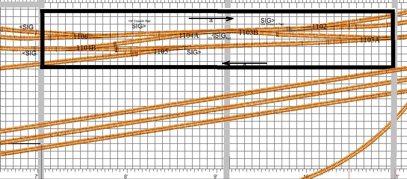
In this case the mainline tracks spaced 2 inchs apart. My normal center
to center track
spacing for mianline track is 1 3/8 inches on the straigntaways and 1
1/2 inches on curves. Here I have used a lightly wider spacing because
I contemplate a small yard building betweeen the tracks. I have elected
to use a single
piece of 1/8 inch cork instead of a system of cork switchpads connected
by cork roadbed strips. This makes for a much cleaner installation and
saves a lot of cork cutting etc. I
begin by carefully locating the centerlines and penciling them in on
the homosote using the XCAD 1 inch grid as a guide. I then pencil in
the
outline on the single, large cork pad (just wide enough for the double
track but not so wide as to cover the location of the 1/2 inch holes I
will drill for the turnout throw rods.) I then cut out the cork pad,
and glue
it
down using white glue. Next,
I draw on the cork - solid mainline track centerlines and doted
lines to
indicate the
location of any supporting cross members in the bench work. Should
a cross member interfer with a switch machine or a dropper, I can mark
a
new location on the cork and move or notch it when I install the
section. Then I again use the Xtrack CAD rendering with the 1 inch grid
and my trunout temples to locate all seven
turnouts, lining up the track centers on the centerline, marking all
railends and all holes to be drilled. Finally, I drill the holes for
the turnout wires and the large 1/2 inch holes in the bench adjacent to
the
edge of the
cork pad for the turnout throw rods, then thread the wires
through the
small holes in the pad, and position all the
turnouts on the center lines using a few track nails to hold them
loosly in place.
 |
Cork glued in place, center lines and
cross memeber lines drawn, holes marked and drilled, and
turnouts installed and tacked down. The turnout in the right foregroud
is not
yet lined up with the center mark, but when it is alligned, the throw
bar will be positioned directly above the large 1/2 inch hole in the
bench most of which which you can see in the shadow just to the
right of the cork
pad in th elower left of the photo. |
Next, I install the connecting sections of straight track, taking care
to follow the plan with regard to the use of insulated joiners. I like
to use a Dremel Tool to cut track. I mark it just wee bit long, cut the
section, and then use the cutting disk to trim the ends until the fit
is perfect - snug for short sections, and a .020 inch gap at the metal
jointer for longer sections. I use a piece of .020 sheet styrene to set
the gap. When
track laying is complete and everything is lined up very straight
and perfect, and all track and turnouts lightly tacked in place
temporarily using track nails, I tack on some 2x4 wooden guards. These
will
rest on the bench and protect the track work when I turn this section
over to in install switch machines and wire everything up.
 |
Completed track work. Note the 2x4
guards tacked in place to protect the track work. The entire section
will rest on these guards when I turn this over to work on the
back. |
Installing Tortoise Switch Machines and
Tortoise Interfaces on the Prefab Section
6-20-2016
Now that the cork is glued down and the track is all installed,
connected, aligned, and tacked down, I can flip the entire section over
and install switch machines and wire everything up. This is where
working on a prefab section really makes things much easier. Installing
Tortoise machines under the bench is awkward and difficult to say the
least, whereas installing these units on a prefab section, where you
can
flip it over on the workbench, is much easier. I just put the
Tortoise
in the center of its throw, thread the throw rod into the pre-drilled
1/2 inch hole and through the tiny hole in turnout's throw bar, and,
manually moving the tortoise throw from one side to the
other, adjust the unit's position until you get good snug, point
contact on both sides. A shaving mirror and a work light stragically
positioned below the bench help me to observe the points of the turnout
to ensure perfect action as I manually move the Tortoise from side to
side. When the Tortoise is perfectly positioned, I mark the four
holddown screw
positions,
drill the four holes and mount the Tortoise. Since I am using 3/4 inch
plywood and 1/2 inch homosote, I use a length of .032 inch music wire
(spring steel rod) instead of the .024 wire that comes with the
Tortoise, which is not long enough. This gives me the added
length I need plus a little more tension on the turnout throw bar.
Once the Tortoise machines are in place, I add strips of cork roadbed
along the sides on the installation with narrow slots under the turnout
throw bars. I then drill the holes for the dwarf signals, solder the
green and blue droppers to the legs, and install the signals feeding
the three wires through the holes. Next, I follow the steps outlined in
my post of 3-4-2016 to wire everything up. At this point I attach
labels to three sides of each Tortoise machine, and to each tortoise
interface barrier block cover, and to the points where each set of
track wires penetrate the bench. I then use my
multimeter to check the electrical continuity and correctness for all
rails and frogs and dwarf signal outputs in both the thrown and closed
position for all turnouts. While I am doing this, I do a little extra
labeling to help make serving each interface a little easier should the
need arise. This involves marking the mainline (closed) position of
each Tortoise throw bar both on the Tortoise machine and on the bench
next to the machine, and marking on the bench at the penetration all of
the blue (+) LED wires ti indicate which supplys the red and which
supplys the green leg of the LED. I also mark on the tortoise and on
the bench next to the Tortoise the side of the Tortoise edge
connector whose outermost contact is the positive power to the Tortoise
Machine (white wire in my color scheme).
Note: I have experienced some intermittentcies in
the connection and in the solder joints to eight position edge
connectors, so I check the frog continuity and the dwarf lights
while manually wiggling the connector around by the wiring harness to
be sure all connections are solid. The photo below shows the underside
of the
prefab section with the 7 turnouts and 7 Tortoises and 14 dwarf signals
wired to the interfaces and labeled.
 |
Seven Tortoise Machines with
labels and track wired up via Tortoise interface barrier
blocks..If you look very closely at the thrid and forth barrier block
in this picture, you can see some of the 30 agw wiriung
for the
layout lights, which I later ditched in favor or more robust 20 agw
wiring.
|
After working with the 30 agw wrapping wire, I quickly realized that
this was a bad plan - the stuff is just too delicate and too
tedious
to work with. So I ditched the 30 agw in favor of a more conventional
22 agw blue and green wire hook up that employed a single sub-bus
feeder pair off the main 5 volt supply bus and a daisy chained
blue/green parallel circuit to the
lighting inputs on each of the seven Tortoise interface barrier blocks.
This involved re-wiring all the dwarf signal LEDs, drilling new holes
large enough to accommodate the 22 agw wire the
same way I handled track droppers. This required the holes with the
outer two slightly angled
and then bending the LED
legs to conform to the wider three hole array.

|
Here is the nearly finished section
with the
dwarf signals illuminated. I have yet to install sleepers to replace
those removed for rail joiners. Also, notice that I have added a line
of cork
roadbed with narrow cutouts under the turnout throw bars and dwarf
signals along the sides of the intalllation. In additon I have drilled
1/2
inch holes to accomodate future signal masts. (See the my entries
regarding
signal placement 2-24-16 and 7-4-16.) |
I am now ready to install the feeders to the input side of the Tortoise
Interface Barrier Blocks, which I can do if I mark and measure the
exact
locations of the DS64(s). I mark
the position(s) on the underside of the prefab section so I can line up
the DS64 later, and then proceed to
measure and cut feeders - for track power - the distance from the
tortoise interface barrier block to the edge of the section + the
distance from the edge of the section to the edge of the bench once the
section is installed (less 4 inch for the mounting board/bench edge set
back) + 8 inchs for a service loop behind the bus wire
mounting board + the distance down
the bus wire mounting board to the appropriate red or black track power
bus + 10% for trim. For lighting sub-bus feeders, the same. For DS64
outputs the same + the distacnce along the wire mounting baord to the
DS64 mouting board.
All that is needed now is to install thin sleepers at the
points where they have been removed to make room for track
droppers
and/or rail joiners, and to solder all the conductive metal rail joiner
connections and paint those joints and the plastic joiners as
well. I use a dremmel cutting disk to flatten
the sleepers so they slip easily under the rail joiners without lifting
the track, and a dab of white glue to hold them in place and a dab of
gray paint to match the weathering if needed. (It is best to use
sleepers from a weathered piece of track.) I will not solder the metal
joiner joints or paint any rail joints or joiners unitl after the track
is glued down on the layout just in case I want make any adjutments or
alterations.
At first I thought I would solder the metal conductive rail joints on
the back side of the rails - the side away from the viewer, but upon
reflection, this would make it difficult to un-solder them should I
need to take something up or make a change once the prefab sections is
in place on the layout. So I'll make my soldering neat
and keep it on the accessable side of the rail. With the little paint,
it will be invisible.
Testing Installed Atlas Code 55
Turnouts and the Prefab Section Wiring.
6-22-2016
To test this prefab
section, I first
hook up DS64s
and program them to the turnout addresses powering them for the 12 volt
supply on on my special work bench. The two crossovers will, of
course, work in tandem, so for the seven turnouts, I will only need
five DS64 addresses and feeders. I then connect
all the red A track feeders and and all the black B track
feeders to their respective track power bus on my
track laying
bench. Since there are no detection requirements for this route
between detected blocks, the A and B track feeders
can
be daisy-chained and connected to
their respective power buses at a single point.
Now, I just wire
up
loconet to the DS64s and I am ready to run a few test-locos across this
section using my Digitrax throttle.
 |
Testing prefab section track work and
wiring on the the prefab bench using my spare DCS 100, 2 DS64s
and
my Digitrax throttle. |
The running of the locos or even
short trains on prefab sections not only checks for electrical wiring
continuity, but most importantly, it checks the precision of the track
laying. So I like to run one loco of each type in my roster, just
to
make sure they all run smoothly without derailments or hesitations
through each turnout in the section in
both the closed and thrown positions. Backing a short rain through
each turnout is generally a good idea as well. I have found cases where
all but one of my locos ran well in a certain turnout, so it is best to
be thorough in your testing.
One note about the Atlas Code 55 turnouts. Remember, I am connecting
the Atlas turnouts to track power only at the stock rails and the frog,
and relying on the turnout's internal connections to the pivot rails,
the closure rails and the frog exit rails without the additional
hard-wire bonding often recommended by so many experts. So I have to be
careful to fully check the electrical connections to each rail in each
turnout. I found that, after installation, one
turnout had no connection to one of the
point rails, so I fashioned a bond using 30 agw wire. After a little
experimenting I found the failure
was
intermittent, owing to stress on the turnout. Each installed turnout,
when tacked down to the bench, can be placed under a small amount of
twisting stress
by the tension rod in the Tortoise Switch machine and sometimes by a
slightly misaligned installation. This tension can
vary depending of how the Tortoise is installed, so it is best to keep
this in mind, and as you install your turnouts and position your
Tortoises. Try to place them in a
way that does not put undue twisting stress on the turnout because this
twisting might
cause its internal electrical connections to fail or to become
intermittent.
As I noted before, it is best to test a lot of your rolling stock on a
new installation. I had one case where all my Altas locos ran one
turnout fine except one of my big Kato E8s that derailed at the same
spot every time. A very
small amount of filing on the corner of a closure rail - right at the
junction with the end of the point rail - proved to be a simple fix for
the offending loco. This is very delicate business in N scale. Take
your time. MAKE IT ALL PERFECT, AND YOU WILL SAVE YOURSELF A LOT OF
HASSLE DOWN THE ROAD.
Rethinking the Layout Lighting Wiring
Scheme
6-24-2016
The 30 agw wrapping wire had trouble written all over it. Bad plan!
Replacing it with 22 agw made for a much more robust, much more
easily serviceable installation, and using the daisy chained sub-bus
feeder, did away with the need for the layout lighting distribution
blocks. A single feeder pair for each group of LEDs will
be attached directly to the 5
volt power bus on the bus mounting board and a label at that connection
will list the signals or LED lights in the group. I was trying to avoid
daisy chained connections under the bench in favor of a system where
all connections to the bus were on the mounting board, but the daisy
chain seems makes more sense and seems unavoidable in the case of
the layout LEDs.
Signal
Protocol, Programming and Placement
7-4-2016
Now that I have begun to lay track on my prefab modules, I am drilling
holes for mainline signals as I go, so before I drill I carefully
recheck the placement and propsoed function of all mainline signals.
I then check to
ensure that they are correctly placed on the TrainController
switchboard and in all my XCAD files, especially on the detailed
sectional renderings that I am using as guide to lay out track on the
prefab modules.
Signal placement, protocol, and programming is tricky business, so it
is a good idea to work it out, and then after some time has
passed, revisit it for a final check. Proper and consistant
placement requires,
an ironclad signal protocol. Which side of the track is a
signal to be placed on? How many heads, aspects, etc? What do the
colors
actually mean? On real railroads, these protocols vary from line to
line, and from era to era. It is good to do a little reading, but in
the end you have to work out a protocol that works for you. There are
really not set rules.
I use the Digitrax double headed masts with
three aspect heads
(red, yellow
green) to the right of a mainline track and offset by about 1 inch.
A 1/2 inch hole in the benchtop for each mast is perfect, allowing for
the mast to project above and the tiny circuit board to snuggly fit in
the hole below. I use modeling clay to fill the remaining gaps making
any future removal or serviing of the masts easy. Since my benchtop is
1 1/4 inches thick I use a 9/16 drill to auger out about 1/4 inch deep
on the bottom side to allow the protruding connector to fit in the
reccess, and thus allow the full height of the mast to be exposed above
the benchtop.
Electrically these masts can be used in a four aspect mode with a
blinking yellow as the fourth aspect. I prefer to use them in the three
aspect (red, yellow, green) mode, with the top head indicating the
status of the mainline (closed) route through an upcoming turnout and
the bottom head
indicating the status of the diverging (thrown) route. Green indicates
a clear path,
unobstructed by any upcoming turnout positions or by loco occupancy
or reservation through the next two blocks, or to the next signal.
Yellow indicates
that the next block is clear of obstruction, but that the second block
ahead is either occupied or reserved or that a turnout after the
first block
but before or within the second is in a blocking position. Red
indicates that the
next block is occupied or reserved or that a turnout before the next
block is in a
blocking position.
Programming signals in TrainController is as straightforward and at the
same time as flexible as this kind of thing can be, but it is often, by
its nature, pretty confounding, so I take my time and try to conider
all the possibilities. I am currently
visiting family and away from my shop, so with a lot of downtime over
the next few days, I am programming signal triggers for theA&BR2 in
TrainController off line on my laptop.
Breaking
Ground
7-5-2016
At last! We broke gound last Thursday. Here is the first photo of the
new train room.

|
First photo of the new train room.
7-5-2016 |
Tortoise Interfaces on a Prefab Module
7-8-2016
I am continuing to construct prefabricated modules, laying track
and wiring turnouts. Here is a photo of the underside of a simple
module (a mainline crossover and one siding switch - three turnouts
with
three Tortoise machines, and five dwarf signals.) I have yet to install
feeders on this module. Notice the service loops on all droppers. I
construct droppers by soldering 20 agw insulated wire to 3/4 inch
lengths of uninsulated 22 agw bus wire that is soldered to the bottom
of the rails of a section of track or the rails of a turnout,
or to the turnout frog ring connection on the Atlas Code 55 turnouts; I
solder
my 20 agw droppers directy to the legs of LEDs in the case of
layout lights or dwarf signals. Since my
bench top and roadbed is 1 3/8 inches thick (3/4" plywood, 1/2"
homosote, 1/8" cork) these solder joints are
hidden and
insulated in the bench-top pass-through-holes,) I always create a small
service loop to facilitate future accessing these solder connections
and to
make it easy to free up a section of track or a turnout should the need
arise.
 |
Prefab Module on the work bench with
Tortoise Machines and Tortoise interface and track (red, black),
frog (yellow) and LED
dwarf signal light (blue+, green-) droppers attached. Note
the small service loops. |
Footings Poured Today
July 13, 2016
Block Walls - Train Room Takes Shape
7-28-2015
Foundation Walls
Complete
8-11-2016
The foundation walls are complete, reinforced with rebar and filled
with concrete. Waterproofing is under way, and they are preparing
to pour the slab. Notice the 3" conduit under the floor. This
will connect all the "along-the-wall" bench work to the center section
bench work and thus allow me to locate the booster in the center of the
room and minimize many power bus wire runs.
 |
Track
Laying Using Xtrack CAD
8-17-2016
Xtrack CAD is a pretty remarkable program, and its free. It takes a
little time the get fully facile with it, but once you get the hang of
it, it can be great help in creating perfect track work when using flex
track. Among other
things, it will monitor all radii and grades to insure you have not
gone above or below your set maxs and minimums, create perfect
track alignment and spacing, and automatically calculate and
insert easements and curves. If you use the automatic track joining
feature, the program will not let you join two sections until the
positioning of the sections to be joined is correct, and then
it will insert all the segments needed to join your sections, including
any easements, while allowing you to control the size and sweep of any
radius to be inserted.
As I mentioned in an earlier post, I use detailed Xtrack CAD
renderings to layout the prefab sections I am now building. Some
modelers printout 1 to 1 full scale pages and paste them to the
homasote and lay track right over the top them. For me, a large scale
print out (say 6 to 1 or so) with the grid set to 1 inch allows
me to locate track on the homasote surface with very precise accuracy.
The print layout routine in Xtrack CAD is a bit difficult to master,
but again once you get the hang of it, it is great.
 |
Here is an Xtrack CAD printout of a 48x
8 inch prefab section with my notes for locating track, turnouts,
and cross members of the bench. This gives me accuarcy down to about
1/8 of an inch, and sould any finer adjust be needed, I can take care
of it when I position the prefab section on the bench work.
|
September 2016
Slab
Poured
9-7-2016
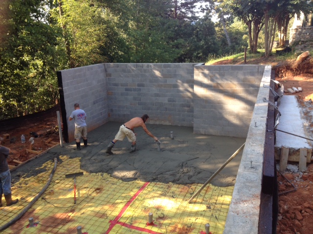 |
Concrete finishers at work in the new
train room. We should begin rough carpentry soon. |
Painting Figures
9-10-2016
I have completed all of the prefabricated track sections except one,
the long section that will contain the two mainline tracks and a
parallel section of the yard lead and ladder at Altamont Yard. I am
still giving thought as to exactly how I want to built this last
section.
In the the meantime, since I like to place all of my bridges, bridge
abutments, and station platforms as I lay track, I have bridge kits and
station platform kits to
build. I think I will start with the platforms, and I'll start that
process by painting some figures to go on the platforms. I generally
buy unpainted figures because I enjoy painting them and because the
painted figures are horribly expensive. I like the Preiser unpainted
sets best (~$23 for a set of 120), but they have been hard to find
lately so I am today using
Model Power sets of 72 unpainted N scale figures (about $8.00 per set),
which are fine. Both the Preiser and the Model Power sets are
160:1. Some other brands
are 150:1. You can use both if you like. The difference is not enough
to notice if you don't place the 150:1 figure right next to the 160:1
on the layout. On the A&BR1, I have one town that is 160 and
one town that is 150. I do not think anyone has ever noticed the
difference.
 |
Here are some Model Power figures being
painted. I hold them by hand and use a piece of duct tape, sticky
side out aroud a small piece of .040 styrene to hold them upright while
drying. Not
pictured is my large fluorescent magnifying lamp.
Since Testors discontinued the manufacture of their Railroad
Colors line. I have been in the process of changing out all my paints
to the Vallejo brand of water soluble flat acrylics. I particularly
like the plastic squeeze bottles, which make it easy. Simply shake it
up, and dispense just a tiny drop of well-mixed paint, without having
the clean the lid and worry too much about the proper resealing of the
bottle. I
think that these paints are going to last much longer than those that
come in little glass bottles, like Model Master. In these plastic
bottles, they seal more fully and easily and appear to be
much less likely to dry up. |
Elevation
Calculator
9-19-2016
One on the nifty things about Xtrack CAD is that, if you enter the
elevations at the beginning and at the end of any run of track, it will
allow you to read the grade % (out to 3 decimal places) as part of the
properties of each of the sections of track in the run. This greatly
facilitates the accurate building of riser supports for roadbed along
any graded run. You just have to do the math. For example, if I have a
12 foot run of track on and even grade with a beginning elevation 2
inches above the
homasote bench top and an ending elevation 4.5 inches above the
homasote bench top, Xtrack CAD will tell me the grade is 1.736%.
So, if the beginning elevation is 2" above the homasote bench
top, the support below the beginning of the run is 3/4 inches above
the bench cross-member (2 inches minus 1.25 inches [3/4" plywood + 1/2"
homasote]), and the next support is to be at the next cross-member 24
inches away, how high above that cross-member should the next support
be to to give me a 1.736% grade? Well, its is 24 inches long times the
1.736 grade% plus the beginning elevation of 3/4" or 1.16664 inches,
roughly 1 5/32 inches above the cross-member and 2 13/32
above the homoasote bech top.
I've written a little program in C# using a form I created in Microsoft
Visual Studio. This allows me to enter the beginning elevation (referencing
either the homasote surface or the top of the cross-member),
the grade % , and the length (distance to the next support). I then
press the "calculate button" and I have the height of the next support,
to the nearest 32nd of an inch, measured either from the homasote top
or from the top of the cross-member.
Cool, huh?
Lighting a Covered Station Platform
9/23/2016
The photo below, taken on my A&BR1, illustrates how
dramatic the
addition of directional LED lighting can be along an open covered
station platform.
 |
A night view of the platform at
Westridge on the A&BR1. Notice how the directionality of the warm
white 3mm LEDs I have selected, creates distinct shadows and
realistic, soft pools
of light on
the platform. |
I have finished painting 144 N Scale figures, and other platform
details
like freight boxes, misc. baggage, schedule signboards, and clocks, and
I have
painted the parts for eight 6 inch sections of butterfly style
platform (Walters #3258). Each section will get four 3 mm LED
bulbs wired in series attached to the underside of the roof so
that, along the entire 24-inch-long platform, there will be soft pools
of
light halfway between all the support posts except outside of the two
end posts.This is accomplished by measuring
and marking the location of the 4
LEDs on the underside of the rooftop, and then gluing the LEDS to
underside of the roof before you glue it on. Use
a good sized drop of CA cement
to glue the 3mm bulbs
in place (If you are using a covered platform that does not have such
a space, you can notch the supports (just large enough for LED
leg
wires) in the center of the roof-support trusses just below the
junction with the roof.
Be sure that you orient all bulbs so that they
are daisy chained + end to - end. When
the LEDs are securely in place, drill two more small holes in
the
platform floor just to the outside of the two end posts for the
vertical power feeds. Then
carefully
solder
the LED legs together where they overlap taking care not melt the
adjacent plastic, glue on the roof, and attach
two vertical 22 agw bare bus wire vertical power feeds up through
the holes
in the platform. The two vertical power feeds are left visible next to
the support, like the kind straight electrical conduits one would
often see on old-style real platforms. You can paint
them if you
like. The kind of soldering
needed to connect all of this must be very quick to avoid melting any
plastic: quickly put a little solder on each LED leg to add a little
extra
tinning at the joint, and then get a little solder on the tip
of the iron and quickly touch it
to the LED legs where you have tinned them. With a little practice you
can get a
very quick bond without ever heating the wires so much that they melt
the
plastic.
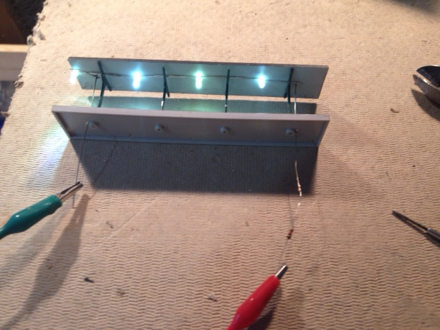
|
Here is the completed underside
light assembly.
Not pretty, but it doesn't need to be, becaue except for the two
vertical "conduits." the wirung and the top part of the bulbs
are hidden from view. |
Note: The choice of LEDs and the single accompanying resistor is
critical. For
this project, you will need tiny 3mm LEDs That emit a soft
yellow/white light. You can calculate
the resistance, if you like, but it is best to build a little 4
bulb-one resistor circuit on a bread board and experiment with
differnet bulbs
and resistor values unitl you get the exact color,
directionarity, and
brightness you like. The LEDs I have selected are from
Newark (MCL 034SWC: LED, T-1 (3mm), Warm White, 3.7 cd, 36 degree,
20ma, 3.4v - $.39 each). They are a nice soft warm color, and very
directional so I get my
nice pools of light. Each bulb is rated at 3.4 volts forward, but they
seem to work fine in parallel groups of four with
a single 1k ohm to 10k reisitor (depending on how bright you want
them) on
the auxillary switchable 12 volt circuit.

|
Testing four 3mm LEDs on a breadboard
using a 10K
resistor
hooked
to 12 volt supply. |
After it is all put together, you may need to adjust each LED so it's
pool of light falls in the exact center of the platform. Since you used
a lot of
CA glue, you can gently bend each bulb in place to get the exact
right angle.
 |
A finished 4 bulb platform section. The
concrete floor and the black metal roof both need a little weatherng (
a light black wash for the floor will bring out the pattern on the slab
sections, and just a littel RustAll on the roof will give some
highights and articulate the crimping joints. I
think the LEDs are still too bright here. A larger resistor will dim
them a bit and give me softer, more diffuse pools of light. I am using
a 1K ohm resistor here,. After some experimenting, I settled on a 8.6k
resistor. You have alot of latitude here. |
Floor Joists Installed
9/24/2016
 |
New train room for the A&BR2 - 38'
(widest) x 22' with a 9' ceiling. For N Scale, this is enormous. I
calculate that, if a train were to run a complete loop starting by the
entrance and continuing all the way around the room, back to its point
of beginning, including a loop along the long center section of bench
work, it would travel almost 9 scale miles. |
Contemplating the Completion
of the New Building.
10-30-2016
 |
Roofers and Plumbers next week. Finish
date Jan 1 ????? |
The new building that will house the new A&BR2 train room in the
basement is
progressing nicely. We are fully "dried in," the framing and sheathing
complete, windows are in, the
shingle siding is installed, and all of the exterior trim is compete.
Next week we get the slate roof and some exterior painting, followed by
the hanging of the exterior doors, plumbers, electricians. septic tank
installation, etc. - then sheet rock and interior finishes. All the
while, the masons will be working on the stone exterior, which will
probably take another 6 weeks or so. I suspect that the building will
be
largely finished by the first of the year.
The train room has the 2x4 firing installed and they are ready for
sheetrock on the outer walls. I can now begin
to construct the train room backdrop walls and the bench work and
install train room AC wiring and lights. I had always planned to
hire professional carpenters to frame the backdrop walls
and the lighting sofit, but having watched the pros work for the
past months or so, I now plan to get professionals to build the bench
work framework and my control panel as well. They can make it much
better, and can finish in a day what it would take me weeks
to build. So, I'll have them frame the sofits, the backdrop walls
including the tricky radial corners, and then get the sheet rockers in.
After
that will come the electricians to install the lighting
and all of the electrical outlets around the walls. Finally,
I'll paint the backdrop wall sky-and-cloud murals and the sofits and
ceiling, and then get the carpenters back in to build the basic
bench-top framework and legs. After that will come the electricians to
install the lighting
and all of the electrical outlets in the bench
work,
as wells as the main electrical and lighting switch panel.
Train Room Lighting and Electrical
Control Panel
10-31-2016
All
the electrical in the new train room will be switched at a control
panel by the computer control panel excedpt of the power to the HUE
lights. There
will be one light switch by the door to turn on the HUE lights,
which will always come up full daylight white after being turned off at
the main switch.
The main switch panel will be mounted
vertically on the bench work next to the computer control desk. From
this panel I can power up AC to everything, computers,
DDC
boosters and peripherals, including room lights, sound
system, servos
and servo controllers, and all of my power supplies for layout lights,
dwarf signal lights,
and stationary decoders.
Train Room Lighting and AC Electrical Revisited 11-8-2016
It won't be long before the electrician begins work, so I spent the
morning giving a final once-over to the
lighting and AC wiring plan. The original
plan was for 18 T8 dimmable single bulb florescent fixtures switched on
and
off at the control panel. The dimmers will be controlled
mechanacally by a servo motor
which will in turn be controled by custom software that I will
write to communicate with a servo motor control card via a USB
connection. The
18 sockets for Phillips HUE A19 colored wifi-controlled LEDs will be
switched
on
and off at the entrance door and the HUe light's color and intenisty
will be controlled by custom software
that I
will write. In addition, a circuit of 110 volt AC outlets will be
installed around the exterior
walls
for work lights, tools etc, as well as a switchable circuit of 110 volt
outlets switched
on and off at the control panel for all DCC components and all layout
power
buses. This is the kind of set up I have on the A&BR1; but at
the time I built that layout LED lighting technology was in its
infancy, so I spent some time this morning thinking
about replacing the florescents with the new daylight LEDs.
Using 10 watt, 800 lumin LED floods, would be perhaps just a little
cheaper and
much simpler to install than the florescents, and they would run on a
smaller wattage
dimmer. Still, I would need 60 of them to get the same light
output I will get with 18 fluorescents T8s (18 T8 at 2750 lumins
each =
49000 lumins ~= 60 10 watt LED floods at 800 lumins each =
48,000 lumins.) LEDS work better with a dimmer than fluorescents do.
Fluorescents only dim down to 1% and require occasional adjustments,
while LEDs dim virtually fully and are quite stable. The 6500 Kelvin
fluorescents I use give a lovely daylight, but I can get LEDs that
put out 6500 Kelvin as well. Anyway, after a little experimentation, I
found
that the only real problem with the LEDs is shadows. Even if I have an
LED light every foot and a half or so, they still cast multiple light
shadows on the bench top, whereas the fluorescents give a nice,
realistic,
diffuse, noontime light with virtually no shadows at all.
I plan to discuss all of this with a lighting consultant at the
lighting supply company I use, but all things being equal, I think I
will stay with my original plan and use dimmable fluorescents with HUE
light accents and effects. Given my experience with this setup on the
A&BR1, I am of the mind that this is the optimal model railroad
lighting method: the most light with the most realism, the most
complete effects capibilities, and the
best and most complete automated control possibilities (that is,
if you can write your own programs).
Laying Out the Backdrop Walls and
the Overhead Lighting Soffit
11/9/2016
Now that the train room is ready with all the 2 x 4
firing attached to the block walls all the way around the
room, we are
ready to frame the backdrop walls that will support one side of the
bench and to frame the overhead fir-down soffit partitions that will
hide the overhead lighting. All of this framing will be 2 x 4 stud
walls. The backdrop wall studs will be 32 inches on center below the
bench level to allow easy under-the-bench access and will conform to
one of several different plans above bench height as detailed in the
drawings below. These walls will include the 4 foot radius sheet rock
corners. The soffit fir-down partition wall studs will be 16 inches on
center, attach to the ceiling and will dropdown to 6 feet 6 inches
above the
slab floor. These dropdown partitions will effectively hide all lights
mouted on the ceiling from viewers as long as they are very very
short and/or very very close to the bench.
|
Backdrop Wall and Lighting Fir-Down
Wall Sections |

|
XCAD rendering with new
dimensions and details of wall section placement. |
All of my planning drawings so far have assumed the new train room to
be 38 feet by 22 feet, which is the designed distance from block wall
to block wall. With the fired in perimeter walls with their 1/2 inch
sheet rock
to come, the as-built inside dimensions sheet rock to sheet rock is
37'
8 3/8" x 21' 8 1/4". As you can see in the drawing above, I have
adjusted the master XCAD rendering to reflect these tweaks by stealing
a few inches from the access aisles behind the back drop walls. I then
created the simplified drawing below for the carpenters, detailing the
exact location to the framed backdrop walls and the overhead fir-down
partitions. Using these drawings, they can snap lines on the floor
and cieling for the base
plates of all of this framing. We will then double check everything and
then proceed to build the walls. (I used PowerPoint to create
this and some other
drawings in this blog. For creating and labeling simple shapes
PowerPoint is very easy to use and it will export almost any kind of
file, jpeg, pdf etc. whatever.)
 |
|
Backdrop
Wall Initial Framing Completed
11/11/2016
The initial framing of the backdrop wall (shown in brown in the drawing
above and pictured below) is complete. This initial stage of framing is
a simple 2x4 stud wall with studs 32 inches on center including four 4
foot radius rounded corners above the bench. The wide spacing of
the studs in the initial framing will allow easy access to the area
underneath the bench. The horizontal 2 x 4 support rail 39 3/4"
above the floor will support the 1x4 bench framework grid.
The bench grid will have a finished height of 44 1/2" (39 3/4" + 3
1/2" for the 1x4 grid members + 3/4' for plywood top or roadbed + 1/2"
homosote top or roadbed.) The upper section of the wall above the
bench will have studs 16" on center and will be sheetrocked over to
form the backdrop sky-cloud-mountain mural. The above-the-bench
sections of the wall will each conform to one of several different
wall-type designs to allow access to tunnels from behind the backdrop
wall (see the wall sections drawing and the wall type floor plan
above.)
 |
A portion of the framing of the initial
stage of the backdrop wall showing a 4 foot radius corner, the basic
32"-on-center framing.Notice the
access aisle behind the backdrop wall. The drop-down-from-the-ceiling
lighting soffit walls are not yet constructed. |
Final Train Room Lighting and
Electrical Plan
11-28-2016
Now that the backdrop walls are framed, the electrician can begin work
in the train room to install lights and outlets. In anticipation of
this, I made a final review of the train room lighting and electrical
plan,which I have beenworking on,
on and off, for
the past year or so
and
keeping up to date in XTrackCAD. The drawing capabilities of
XtrackCAD are limited, and after review, I decided to use a different
application to create the final drawing for the electricians, so I
exported a to-scale JPG rendering of the train room and the bench work
from XtrackCAD, and I then inserted this floor plan into Power Point,
which I often use for simple drawing and labeling tasks. Over the top
of this floor plan, I created a new scale drawing of the lighting and
electrical in Power Point, showing the exact location of all
fluorescent and HUE lighting fixtures and all electrical outlets as
well as the location of the switchs for each. I further
delineated Phase1 (wiring in the walls and ceiling to be completed
now) and Phase2 (wiring in the bench work to be completed after the
bench work is constructed.)
 |
Final Lighting and Electrical. The long
blue rectangles are the 4 foot long single bulb fluorescent fixtures
and the light blue circles are conventional screw-in sockets for HUE
lights.The squares are double duplex outlets. Switches are marked with
an "S". Each square in the grid = 1 foot. |
December 2016
Lighting
Soffit Framing Complete
12/1/2016
All of the framing in the train room is now complete, except for the
lateral bench support rail, the HVAC crew is here today, and we
are ready for the
electricians and then the sheetrockers.
 |
Standing in a viewing aisle and looking
toward a corner of the train room. The drop-down framing attached to
the ceiling forms deep soffits to hide the lighting fixtures and duct
work. The bottom of the radial corner is about 14 inches above
the future bench top to allow a generous reach-through portal behind
the
curved wall to access the tunnel that will go in this corner. I plan to
sheet rock all the way down to the bench top, and then cut away the
reach-through to match the contour of the mountain. |
 |
More detail of the drop-down soffit
walls. |
 |
A view down the bench, which will go
just below the lowest cross member. Again we are looking toward a
corner radius, and in this photo we can see the access aisle behind the
backdrop walls. |
Final Tweaks to Block and Turnout Names
and
Addresses and to the Power District Layout
12/2/2016
This morning I am going over the TrainController Switchboard
to re-check all my block and turnout names and addresses against
my block
and turnout wiring
labels and my Master Block and Turnout Lists to make sure they all
agree. I have
made a number of changes over the last few months, and I want to be
sure all my documentation got updated. While doing this, I am also
checking to ensure that the naming and the numbering of these blocks
makes sense in the context of their physical locations on the layout,
and that the
blocks in each power district form a contiguous logical cluster
that corresponds to a specific area on the layout. For example, I want
to make sure that all 16 of the blocks in the Altamont
Terminal Power District #90-2 [Brown] [BDL168 #95 with addresses 95-1
thru 95-16] are all in the Altamont Terminal area and that they are
named and address-numbered in a logical sequence vis a vis their
location on the layout. Most importantly, I want to ensure
that I don't have any 90-2 blocks in far flung areas away from Altamont
Terminal.
With a few tweaks, this has all worked out well, with only one block (a
remote spur) that is not contiguous to the other blocks in its power
district and corresponding BDL feeds.
Similarly, I am checking the turnout names and addresses to ensure they
they represent logical spacial groupings and that the sequence of
these
numbers makes sense in relation to the turnout's location on the
layout. I am also checking
the DS64 stationary decoder labels to make sure they correctly
correspond to my list and to the turnouts on the Switchboard and on the
layout itself. Finally I checked the proposed locations of the DS64s
that control the turnouts looking for both logical placement and
the most efficient wiring runs. In short, I want the four turnouts
controlled by each DS64 to be near to one another on the layout and I
want
the DS64 on the wire mounting board as
close as possible to this group of turnouts.
Manipulating Color in HUE Light
Programs
12-7-2016
It has been almost a year
since I wrote the first little room lighting program that emulates a
sunrise on the A&BR1 using my Phillips HUE lights. (See
my post of 4-14-20216.)
I have since
modified this original
application and written applications for sunset and a thunder
storm. In these programs and throughout all
of my initial work with the Q42.HueApi C# reference library, which is
designed especially for HUE light communications, I have changed color
by individually entering, line by line, the hexadecimal strings
that represent the color coordinates of each color I want the lights to
output. So a fade from blue to red/orange in 10 two-second steps looks
like this:
//morph color from blue-violet to red-orange
command.SetColor("9D1BFF");
Thread.Sleep(2000);
client.SendCommandAsync(command);
command.SetColor("C31BFF");
Thread.Sleep(2000);
client.SendCommandAsync(command);
command.SetColor("E91BD2");
Thread.Sleep(2000);
client.SendCommandAsync(command);
etc. to
//red/orqange
command.SetColor("FF1B00");
Thread.Sleep(2000);
client.SendCommandAsync(command);
I noted at the time, that I knew there was a way to employ a loop
to do this, but the hex numbers kind of put me off, and I just never
got around to fooling this or with any of the other ways one can
create colors in the Q42 library. Over the past few days I have been
working on HUE color coding methods, and I have devised a way to use a
loop to accomplish
color morphing tasks using hex strings like the one above. The method
is pretty obvious. Increment
normal integers in the loop, and after each step convert each integer
(r, g, and b) to a two digit hex string, and then paste the three
strings together to get the 6 digit string that HUE uses to specify a
specific color. The code below is an example, although the numbers
here are arbitrary and I have no idea what colors this creates. Working
with RGB in this way requires that you consult a RGB color chart the
get the numbers of the red, green, and blue components for your
beginning
and ending colors and then work out the size of the steps needed, the
number of steps needed, and the
ratios of i for each step. Thus, it is still really clunky, and
since it
moves in a linear fashion for each component, the colors you get along
the may not be exactly what you want or they may not even fall
within
the range of RGB combinations supported by HUE lights, which cannot
reproduce all RGB colors. To be sure, the ratios of i you use could be
arranged to change as the loop executes and thus scribe a non-linear
path, but this starts to get kind of hairy; or you could use several
loops to make things non-linear.
//initialize
new hue client and new lightcommand
ILocalHueClient client = new LocalHueClient(ip);
client.Initialize(AppKey);
var
command = new LightCommand();
//declare and define integer and string avrriables
int r = 27;
int g = 0;
int b = 120;
string rString;
string gString;
string bString;
string color;
// loop - incremental color calculation, tranformations to hex and
commands with 2 sec delay
for (int i =
0; i < 25; i = i + 5)
{
r = r + i ;
g = 0;
b = b + (i * .5);
rString = r.String("X2");
gString =
g.String("X2");
bString =
b.String("X2");
color = rString + gString+ bString;
command.SetColor(color);
client.SendCommandAsync(command);
Thread.Sleep(2000);
}
Fortunately
there is a better way. There is an "xy" system based on the
CIE color chart. On this chart all of the colors are expressed in
terms of the x and y axis
(numbers between 0 and 1). The Q42 web page also indicates area on this
chart that are supported by HUE lights. So a nice deep blue
might be (.2, .2) and a red/orange might be (.5, 3.5). So using this
system, the loop to get from blue to red/orange in 30 two-second steps
would look like this:
x = .2;
y = .2;
for (i =
0; i < 31;
i++)
{
x = x + (i * .01);
y = y + (i
*
.005);
command.SetColor(x,y);
client.SendCommandAsync(command);
Thread.Sleep(2000);
}
This is a much
better approach in every regard. I created a little application with
two
trackBar sliders each with 100 increments (0 to .99) in order to
preview all the colors on the chart using the lights themselves. This
is a big help because the color the light produces is not alway exactly
what one would expect when looking at the same color on a color
chart.
The use of the timing "sleep" pauses in these loops ( and indeed after
all commands to HUE lights) is critical. The
HUE
lights are slow to react, and without adequate pauses. the system
may miss steps and then catch up
resulting in visually jerky color transitions. I recommend at least a
1000ms delay after any command.
Construction Blues
12-22-2016
I always find the construction process maddening. It seems as though it
always moves from one disaster to another in a series of unpredictable
jumps and starts that scribe a two-step-forward-one-step-back arc. It
is always over budget and always behind schedule. That is just the way
it is. Progress has been slow, but the quality of the work is
excellent, and yesterday we passed the rough-in inspection, which means
the electrical, the plumping, and the HVAC are all roughed in, and we
are ready to begin finishing the interior - insulation first and then
sheet rock and finally the finished trim, floors and tile. In the
meantime, we have had
some problems with the subterranean waterproofing and all the backfill
had to be removed and the block walls had to be re-treated. Also the
exterior
stone work has progressed excruciating slowly and is nearly 100% over
budget. Still, while I am generally very happy with the result, I am
beginning to get impatient to be done with the dust and the mud, and
I want to return to my normal life. Most of all, I am anxious to begin
work on
the A&BR2.
I think the interior finishes will go quickly, but finishing the stone
work will probably take another 6 weeks, and then another week or two
to finish grading and lay the cobbles in the court yard. So perhaps
early March? Just in time to plant a little grass and some
shrubs.
Or at least one can hope.
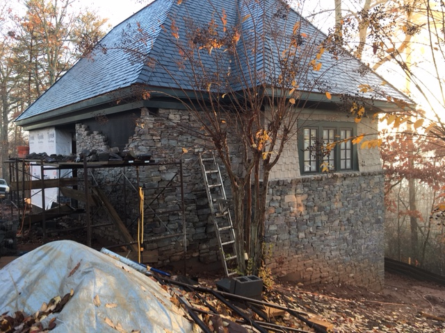
|
January 2017
Wait Time Preperations
1-18-2016
It is frustrating. As the new train room nears completion, I am anxious
to get started, but unable to begin. Still there is plenty to do, if I
can force myself to address some rather long, arduous, and tedious
tasks. For one thing, I have 300 30 inch sections of Atlas Code 55 Flex
Track to weather; and for another, I have 50 more dwarf signals to
construct. I began working on weathering the flex track yesterday. My
goal is to weather five or ten sections a day for the next month or so.
Working in batches of five or ten, it takes a lttle over ten minutes to
weather one section. Along
the way I will construct the 50 dwarf signals in two batchs of
twenty-five. Divide and conquer.
 |
Using dark brown and a light tan
"camouflage color" and a medium gray primer, all in spray cans, I put
on a heavy coat of the dark brown making sure to coat the side of the
rails, followed by a misting of gray and then of tan., wiping the
rails clean immdeiately after each coat. Check out the 6-8-2016 entry
in this blog for details regarding my technique. I then paint the
spike-heads rust color and use a slightly
dried out felt-tipped marker and a straight edge to dark the oil stain
line in the center of the sleepers. |
February 2017
Train
Room Takes Shape
2-4-2017
The sheetrock in the train room is hung and taped. At last, things are
beginning to take shape. The next moves will be to skim, sand, and
prime,
and then, before the bench work goes in, to install the lights and
other electrical in the walls and ceiling, and to paint the
aisle ceilings and lighting soffit aisle-sides black and the
backdrop and the inside of the lighting soffit sky-blue. Next, I'll
construct the basic open frame bench work, bench legs, and install
the wire
mounting board. Finally I'll complete the AC wiring in the bench
and
construct the control panel cabinetry. Then I'm ready to begin
layout wiring, construct roadbed, and lay track.
 |
Creating Signs
2-15-2017
The Southern Railway used "head-of-train" stop markers to position a
train at a platform. I think the protocol was to use a "S" sign for all
trains, or to use a number (e.g. "5") marker for trains with a specific
number of cars. On the A&BR2, I'll use "S" signs with a red cap to
indicate the locomotive stop position beyond a platform. Like the
prototype, I'll also use "W" markers with a yellow cap to locate the
exact point before a crossing where a warning whistle is to begin.
Finally, I will use numbered signs with a white cap to identify all
turnouts by their name, which corresponds to the turnout's
loconet address.

|
Straight pins painted white with signs
made in
MicroSoft WORD using the table function printed on light card stock.
Turnout signs are two sided, "S" and "W:" sign are one-sided. |
March 2017
Train Room Initial Wall Painting Complete
3-19-2017
Progress on the new building is excruciatingly slow, but the end is in
sight. The painters were at work in the train room last week; and with
a little more
electrical work, I will be able to begin constructing the bench work.
In the meantime, I'll begin painting clouds on the backdrop walls.
 |
Here is a photo of one corner of the
train room. The backdrop walls and the lighting soffit above the bench
are painted sky blue and inside of the soffits are painted black
above the viewing aisles. The bench will be 44.5 inches above
the floor. That is even with the top of the open stud wall on the
left. It separates the behind-the-backdrop service aisle from the
train room and allows for under-bench access from both sides of the
bench. |
Painting Clouds
on the Backdrop
3-20-2017
At last I am at work in the train room, and it really
feels good after nearly two years of planning.
My first step will be to paint clouds on the backdrop all the way
around. Since there are almost 120 running feet of backdrop, this will
take a while. On the A&BR1, I created very simple, very
stylized tall,
light cumulus clouds. I painted them first, and then added my layers of
mountains that form the horizon on top of them, so the illusion is that
the clouds' rise from
behind the
mountains.

|
Keeping
the backdrop simple. In this
scene on the Altamont and Blue Ridge 1, there is a tree line at the top
of the rise of the 3 dimensional hill in the distance, then a cut-out
mountain made by gluing foliage 1/2"
homasote, and finally two layers of hazy, distant mountains painted
over
the
clouds on the back drop. This gives the illusion that the clouds are
rising from behind the mountains. |
On the A&BR2, I again plan to paint cumulus
clouds but with a little more detail and depth.
 |
The very first project on the
A&BR2: painting clouds. John Constable, move over! |
I'll paint the sky below the cloud banks a
lighter shade of blue, and I'll feather this lighter color into the
darker sky above in the clear sky patches between the cloud banks. This
overall approach should enhance the illusion
of depth.
 |
I am no great mural painter, but
I was able to get pretty good results after a bit of practice. I got
a panel of sheet rock, cut it into 24 x 36 sections, and painted them
the
sky color. Then on the Internet I read articles and watched
videos regarding cloud
painting techniques. Most of these tutorials deal with painting with
oils or acrylics, so I had to alter the technique slightly to
work with plain old flat latex wall paint and larger brushes This is
not rocket science, and after a few trys,
I got the hang of it, and developed some techniques that work
pretty well.
Notice here my utility work cart (a restaurant busing cart) with two
lighting posts clamped to the side. This supplies plenty of space to
keep brushes, paint, water-wash, rags, sponges etc. close at hand.
Normally
I use this cart for tools and stuff I use regularly in the
train room. Without the lighting posts, it rolls right up under the
bench and is very handy especially when
working in places where the layout is nearly finished and there is no
place to
stage your tools, paints, glues, landscaping materials
etc. Highly recommended. |
I'll not add the distant
painted mountains now, as I like to wait until
the landscape is contoured and then, working front to back, I can
fashion a believable transition across the point where the backdrop
attachers to the
bench.
Rethinking Painted Clouds
3-26-2017
After painting several large clouds
like the
one above on about 20 feet of the backdrop mural painting,
I began to get a bad feeling about the arrow-straight cloud bottoms at
a uniform height. They look like soldiers in a row - unnaturally
predictable. The technique is good , but the composition is flawed.
 |
Clouds in a row. This just isn't
quite right. |
My idea was to have the clouds float above the
mountains, but this "soldiers in a row" impression worries me. After
observing clouds in nature, searching the Internet again to
look at backdrop painting work by
others, and studying a few famous landscape canvases, I have
decided that it
is best to do away with the perfectly flat bottoms and to paint
the cloud banks all the way to the bottom of the back drop, thus again
reverting to the illusion
that the clouds rise from behind the mountains. When the layout is
complete, a
good portion of the bottom of these rather large new cloulds will be
covered by mountains.
 |
Here's the revised effort. This should
work much better. I know this looks like a lot of coulds, but over half
of the bottoms of these will be hidden behind the mountans when the
scenery is competed.
This work is
very forgiving. If you want to change something, just lightly sand the
surface of the old pianted cloud, paint over it with the sky color, let
it dry, and
start over.
|
The mountains will cover anywhere from 8 to 15 inches of the bottom of
these large cloud banks, so they will not be so overwhelming and the
end effect
should be good. Just ot be sure, I will build a short, little,
mock-up section of the bench with a few sturctures,
and some mountains made with homasote and styrene cut-outs.
Then I'll tack it in
place. This will allow me to fully access my new cloud painting
approach
before painting the rest of the room.
Working Drawings for the Hinged
Bench Tops at Altamont
3-25-2017
It has been almost two years since I did the first drawings for
the hinged bench tops that will allow access to the hidden yard
below the City of Altamont (see post of 9-7-2015). Now that the
backdrop walls are complete, I have made detailed drawings for the
construction of these hinged bench top sections. On the Type B wall,
where there is access to the track underneath the city from behind the
backdrop wall, I will hinge the bench top section from the stationary
raised double track runners on the aisle side of the bench. On the Type
BB wall with no access from behind, I will hinge the bench top section
from the backdrop wall so it will open the other way and allow access
to track underneath from the viewing aisle.
 |
This section will hinge from the
stationary riser supported by the 2 x 4 braces to the right. The hinged
section will allow the City of Altamont to be laid out on a terraced
parallel grid, three stepped terraces, each 1.5 inches above the next.
The lower, stationary terrace will accommodate the mainline and
the siding, a row of warehouses and stores, and finally a
street next to the bench edge. The middle level will accommodate
two rows of buildings facing the main street (a divided two lane
affair with a streetcar track in the center). This layer will have to
be notched at the cross-street intersections to allow for rather
steep streets going down to the level below. The upper level will
accommodate two rows of buildings facing a 1.5 inch, two-way street
(the
back row of buildings will be narrow "background" buildings), and there
will be homasote cut-outs to form two tree lines set out from the
backdrop wall. Note that the first four tracks next to the wall are
part of a grade not shown in this drawings. This will require me to
notch the 1x4 above the highest terrace level. |
 |
The hinged bench top to access the
rest of the track below the city of Altamont will hinge from a 2x4
runner nailed to the
backdrop wall. This will allow access to the hidden yard from the
viewing aisle side of the bench. Note that there is no upper level
here, only open bench frame for low hills The city will
narrow here for a residential district on the north side and a
warehouse district above Altamont Yard on the south side. I plan to
fashion this so that I can stand in the opening between the track next
to the wall and the lower terrace level when the cover is
open. |
Elavuating the Painted Clouds on the
Backdrop
3-27-2017
Just to make sure my towering cloud banks on the backdrop
work
with the scenery, I have constructed a little mock-up using a piece of
homasote at bench top height as a temporary bench top, a couple of
rough
mountain cut-outs, and a few half buildings designed to fit right up
against the backdrop. Rough and crude as this scene is, the clouds
against the new clouds against the mountains work pretty well in
this context, so I will continue painting.
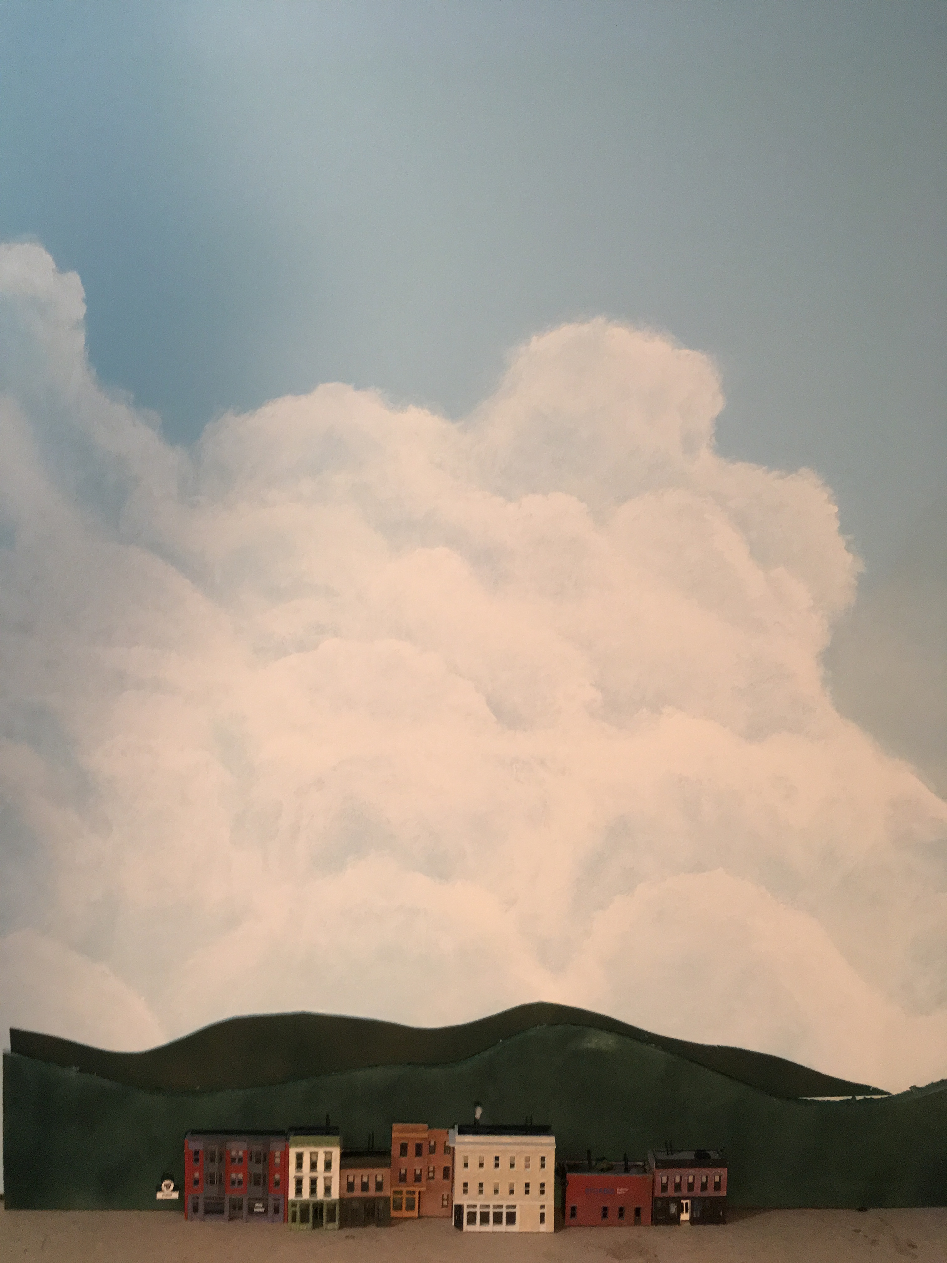 |
This this a very crude rough-in,
but my new cloulds seem to work pretty well against the mountains,
especially since
this is a a mock-up at bench top height. Many of the strucutures on the
layout
will be at higher elevations than this, up to 8 inches above bench top
level, and
some of the the 3 dimensional mountains will rise above
that. So in spots, only the top of the cloud bank will be
visible. |
April 2017
Working with Mountain Silhouettes on
the Backdrop
4-1-2017
I am well over half way done painting clouds, and I should finish next
week. Before I move on, I think it is now good time to work
out the way I want to handle the mountain forms on
and against the backdrop, even though I'll not be putting any mountains
on the backdrop any time soon. Their exact positioning and coloring
will depend on the 3 dimensional scenery on the layout in front of
them.
Still, it is a good idea to work out exactly how I will proceed when
the
time comes, and once I work this out, I can create a more finished
looking, to-scale mock up to re-check the look of my clouds against
mountains in a more fiinished form.
On the A&BR1, I used a 6 tier system.
.
 |
Layer 6
was a low tree line made with homasote painted dark green and covered
with clump foliage. Where I could, I placed this cutout tree line about
1/2 inch in front of layer 5 which is screwed to the backdrop.
Layer 5 was a 1/2 inch homasote cutout painted dark green
with clump foliage glued on. I sprayed this with a duller, less vibrant
green and little gray for distancing.
Layer 4 was a .040 styrene cutout painted dark green with ground
foam glued on, and then spayed painted to look kind of misty.
Layers 2 and 3 were misty painted .040 styrene cutouts.
Layer 1 consisted of one or two ranges of very distant mountain
silhouettes painted
right on the back drop. |
On the A&BR1, I struggled to find a satisfactory method for
attaching my cutouts to the backdrop wall. I wanted to to move them
around to get the positioning just right and then attach them in a more
permanent way. I tried double-sided tape, various glues, sheet rock
nails. In the end I got things in place, but the methodology is not
consistent.
Upon reflection, I now think the best appraoch on the A&BR2 will be
not to paint
mountains on the wall at all, but rather to use painted, thin, .020
styrene cutouts for my distant mountains, and then to attach all
of my cutouts to the thicker homasote or 1/2 inch plywood layer in
front, first using
double-side tape for positioning, and then using very spot glue
welds, short screws, or staples for the permanent installation. This
way I will end up with a nice
sturdy, removable, homasote and styrene sandwich which can be attached
to the wall with two long sheet rock screws - neat, clean, modular,
easy to
remove and to change around and adjust.
I also want to experiment with the painting technique for the middle
layers of styrene cutouts - perhaps a little more detail, perhaps
I can develop a technique for painting mid-level silhouette cutouts
that looks better than the foam covered cutouts. Perhaps fewer
layers will look better. (Contined: See entry of 4-4-17)
Testing the HUE
Lighting System in the New Train Room
4-2-2017
One of the things that has been on my mind regarding the lighting
scheme in the new train room involves the distance of the new building
from my house and the range of both my WIFI home network and the
HUE control bridge. This morning I took my little WIFI range extender
out the new building and plugged it into an electrical outlet in the
bedroom closest to the house, which is just above the train room.
It acquired the WIFI signal nicely. I then plugged the HUE bridge
directly in to the WIFI extender, and went down stairs and plugged in a
HUE bulb in the train room. With all of this in place, I used my laptop
to wirelessly connect to my WIFI Ethernet home network, and once
connected, I ran one of the programs I have written to
acquire and address the HUE bridge. Viola, it all worked fine. I am not
worried about HUE bulbs elsewhere in the train room, because if any
bulb gets a signal, it will relay it to adjacent bulbs.
Working Drawings for the Bench
Work
4-3-2017
Since the froward edge of the bench work lies directly below
the aisle-side edge of the lighting soffit, it will be any easy matter
to lay out the bench on the floor using just a plumb bob and a chalk
line, a bench work plan is not really necessary. All that is needed is
an elevation drawing of a cross section of the bench detailing the
various sized lumber and plywood components. I have also included a
detail of the concave and convex bench-corner construction.
 |
I have not drawn all the lateral
supports, which will be initially tacked in using sleet rock screws.
These will be 2 feet on center and will later be adjusted where needed
to accommodate switch machines etc. |
 |
Bench work cross section detail |
|
Bench work corners |
Further Thoughts Regarding Mountain Silhouettes
4-4-2017
As I paint clouds on the backdrop, I have been giving some thought
to the mountain silhouettes that will go in front of them, and I have
boiled this
down to five elements or five layers if you like. Closest to the
viewer, there will be either a 3 dimensional mountain that abuts the
backdrop wall or a low tree line (about 3 iches high), which will be
made by gluing coarse
clump foliage to
painted homasote or 1/2 inch plywood. Ideally, this first homasote tree
line
silhouette will be attached to the bench about 1/2 inch out from the
backdrop wall. This 1/2 inch space adds depth and allows a space to
place small silhouettes of distant buildings, steeples, water towers,
or smokestacks etc. but to be effective, it must be viewed from the
front. On the A&BR2 there are many places where it is possible to
look down the line of the layout, and in these cases the space is
visible. This is not ideal, so in many places I will use only 1/4 of
space, or even attach the tree line cutout to the first mountain
cutout. Next, there will be a thick mountain silhouette against
the backdrop wall with coarse foliage glued to a painted (black)
1/2
inch
board. Behind that, a painted .040 styrene cutout with fine
foliage stapled onto it, and behind that, maybe a .040 styrene
sheet
with green turf glued to it. (I want to experiment with painted
highlights and shadows on the glued-down clump foliage layers and on
the turf
textured layer as well. On the A&BR1, I used the truf covered
cutouts, and I am not totally happy with the look of these. Still,
there may be a way to highlight these
with paint and make this technique more effective) Finally, a
painted mountain cutout depicting several layers of
distant mounts on 020. styrene cutout (This
layer will
require some painting technique to create distant misty mountains
with solid
light blue very distant mountains behind.) I also want to
experiment using light gray and light blue spray paint to achieve
increasingly
misty ranges front to back.
For more information about this technique, see my tutorial "Marrying
the Layout to the Backdrop" elsewhere on the web site. This tutorial is
all about developing methods to effectively hide the point of
transition from the 3 dimensional layout space to the flat painted
backdrop. The layered mountain cutout technique makes this transition
very gradually in the last inch or so of the 3 dimensional space.
When you think about it, the actual transition from layout to backdrop
does not take place here until the fianl painted distant mountains.
This is an ambitious scheme, and it will take some doing to get it
fully
worked out. I think there is a danger here of getting things too
complicated, so I'll have to be careful as I progress. Certainly, I
will not use all of these layers in any one spot. I suspect 3 or 4 will
work fine in any one spot of the backdrop. Whatever the case, now seems
a good time to construct a test module, evaluate it against the cloud
backdrop, establish scale and fix the horizon level, and to work
out details and techniques for future construction.
Getting
the scale right is critical. I have spent a good deal of time over the
last few days trying to determine how high above the bench the horizon
should be. This is tricky because in places the 3 dimensional scenery
will rise as much as 5 inch above the bench top, and it might be
unrealistic to have the horizon rise up in all of these spots. In
order to help visualize this scaling issue, I created a
scaled sketch depicting in overview 14 feet of the backdrop
wall behind the town of Fitzhugh. Then I drew to scale what I think
is a
realistic overview of the scene. I next selected a 4 foot section of
this overview, and created a more detailed scale drawing of this
showing all the layers. I will build my 4 foot long test mock-up from
this.
 |
Preliminary sketches. I think a horizin
12" above bench top will work, but I will know better when I get this
mock-up built. Notice that in this section the roadbed grade rises from
3 to 4 inchs above the bench, so with a 2 or 3 inch tree line, this
leaves only from 5 to 7 inches or so for the layered
mountains. |
Working with these sketches and experimenting with rough cutouts, I
have concluded that 12 inches above the
bench will probably work best, except on the east wall where the
highest streets of City of Altamont meet the backdrop 8 inches above
the bench-level hidden yard below. Here, I will cheat the horizon up
to 16.5 inches above the bench. With a roughly 3 inch tree line, this
will give me 5 inches for layered mountains. Since there are
high, 3 dimensional mountains in the corners of the room that
flank both
sides of the City of Altamont hiding the far mountain horizon and
separating this east wall from the
adjoining north and south walls, this transition to a slightly higher
mountain
horizon along the entire east wall should not leap out at the
viewer as
an inconsistnacy.
Once I have the first three layers on my mock-up completed and
assembled, I can work
on the painted layers until I develop a technique
that works and is repeatable. It is clear from this that the painted
layers will
still have to glue either to the wall or to the back of the .040 style
layer, so I will continue to try to find a glue that will not warp the
styrene, set up firmly enough for the long haul, and
still allow me to disassemble these pieces if I decide to make a
change.
In preparation for painting the critical fourth .020
styrene layer, I have
been looking at the mountains around me and watching mountain painting
tutorials on line. Although the below photo is a winter scene taken
from my front porch, it illustrates the terrain I
what to reproduce. I can clearly now see that the mountains on the
A&BR1 a far too steep. The Blue Ridge Mountains are rugged in
places, but
from a distance they present a very soft panorama.
 |
The view from my front porch. A soft
panorama. A summer version of this view is the terrain I want to
recreate.
It is interesting to note the light source is from the right
here. This is a detail I will observe in order to achieve depth and
and interenst and to make images on all four walls appear to
have a single
light source. I have done this already with my clouds. On the west
wall,
the clouds are front-lit; on the east wall they are back-lit; on the
south wall the light comes from the left , and one the north
wall
it come from the right. This is all consistent with a summer afternoon,
with the sun in the Western sky. I can do the same thing with the
mountains. It is a subtle point, but every little detail adds a little
something to the overall effect. |
Constructing a 4 Foot-long Mountain
Silhouette and Checking the Scale
4-6-2017
Below is a photo of the
framework of the 4 foot-long, mountain layer backdrop module, which I
constructed as an in-place test against my clouds to determine scale,
horizon height, and to develop texturing and painting techniques.

|
Here is the painted, roughed-out, 4
foot-long, mountain-layer mock-up positioned next to the future 1.9%
grade at
Fitzhugh, which at this point is between 3 and 4 inches above the bench
top. At its highest points the silhouettes are about 8 to 9 inchs
high forming a horizon that is about 12 inches above the bench top.
This horizon line and the
scale look
good to me. I tried this with slightly higher mountains (15 inches
above the bench) and that did not work as well. There is a 2.5 to
3 inch 1/2 inch ply wood tree line layer in front, with a plywood layer
for clump foliage behind
that; next a .040 styrene layer that will be covered with fine
foliage; and finally the .020 distant blue mountain layer, upon which
several nearer ranges may be painted. At this point all the
silhouettes are painted black except for the distant light
blue mountain silhouette in
the back. The application of various shades of
foliage, misting with spray paint, creating shadows on the side away
from the sun (in this case the left side) and painting highlights will
follow. |
Continuing with the construction of the 4 foot test mockup, I next
added some Woodland Scenics clump foliage to the first two layers. In
the photo below we see the tree line and the first layer of moutains
covered. The next range of mountians (which will get finer foliage)
and the light blue distant mountain cutouts are uncovered and
unpainted respectively at this stage.
 |
Here the tree line, which is
tight-up against the first layer of mountains with no space in between,
is covered with medium green clump foliage with a good bit of light
green foliage mixed in, especially along the top. The light green top
helps to highlight the silhouette and to articulate it from the darker,
more uniformly colored
layer of mountains behind, which are covered with a combination of
medium green and dark green clump foliage. I think when I mask and
apply a little spray paint I can make the tree line stand out a bit
more by highlighting the top of the tree line with a little very light
green or yellow and by spraying a subtle mist of gray on the
first layer of mountains behind. The second range of mountains behind
that, which will be covered with finer foliage and will be sprayed with
even more gray and some light blue, and the next range, which will
either be painted a
misty blue-green-gray color (or perhaps
just a flat color or perhaps with more painted detail) in front of
the light blue horizon ridg . Since this
mountan layer "sandwich" is not attached to the wall at this point and
since all of these layers easily come apart, all of this spary painting
can be done on my paint-bench and the masking or shielding from layer
to layer will be easy. Once I establish the spraying shades for the
different layers, future layers can be sprayed before assembly and
there wil be not need for tedious shielding or masking. |
Rethinking
the Tree Line and Completing the Mountain Mockup
4-11-2017
The more or less flat, uniform tree line layer on my Mountain
"sandwich" is not working fully for me. I have used this technique on
the A&BR1, but I always had a row of low buildings in front to
break up the regular shape. Here the track will be pretty much right up
against this tree line, so no nearer modeling can be inserted in
between. To solve this, I have decided to add a flat photograph on the
forest floor in places along the length of the tree line. Below are
photos detailing this simple process.
 |
Here is the "before" - a straight
uninterrupted tree line right down to the future roadbed. |

|
Here is the cut out to be pasted in
- a photo I found on the Internet and sized, cropped, and
retouched in photshop to make it the right scale and soft,
dark, and misty. This is printed on 110 point card stock. |

|
Here is the "after"
photo with the photo cutout in
place. I glued
on a few 3 dimensional tree trunks made from painted wire, toothpicks,
and
kitchen skewers to establish a foreground and to push the misty photo
to the back. Finally, a few clump foliage bushes at ground level break
up the
straight line on the bottom of the form. |
Below is the completed 4 foot section in place against the backdrop,
with the light green highlight sprayed on the top of the tree line, the
next
layer of mountains sprayed with a little medium gray to give it a
little distance, and the next layer of mountains covered with course
turf and sprayed, first gray, and then liberally with light blue to
enhance the contrast and add more distance. Also I altered the clouds a
bit to better frame the scene. Not Bad. I am still a little unhappy
with the look of the next to the last layer, that is the .040 styrene
layer covered with corse truf. It is a little ragged looking and the
coloring is not yet just right. It work OK where we just see the the
top edge of it, althoug it could be lighter still in color. However,
where there is a large portion of this mountain exposed, it looks
uneven in texture. I will continue to experiment to refine the
technique for this layer. The rest looks good to me.
 |
After a bit of experimentation, I found
that the mountain module looked best without the extra layer of
far
mountains that I had planned. The light blue cutout looks
great against the clouds. Adding another layer in front of it, no
matter how well painted, proved distracting, So I'll keep it clean and
simple. I have not added the shadows to any of these mountains to
establish the light source as planned. I may experiment with that
later, but something tells me this will work better without that
complication. |
Around the layout, the foreground will vary, so all of these
modules will vary to accommodate what is in front of them, but this is
the
general model I will follow: at low tree line, a near mountain
range of
clump foliage, a misty medium-distance mountain range of corse turf,
and a
distant mountain range painted solid light blue.
Cloud Painting on the Backdrop
Complete
4-13-12017
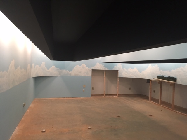
|
The completed clouds may look a bit over-the-top, but remember
only
the top half or so will show once the mountains and the foreground
scenery is complete. Also I will re-touch each section of clouds
to fit the scenery in front just as I did with the 4-foot section
above. (The cutout section of wall on the far side is for
behind-the-backdrop hidden yard access under the City of Altamont. This
may be higher than needed, and so I may sheet rock over some or all of
this depending on the clearances afforded by the hinged top that
will go in front of it.) |
Test Section of the Bench Completed
4/18/2017
The first section of the bench work for the A&BR2 was completed
today. The 8 foot section allows me to evaluate the new bench
height (44 1/2 inches from floor to the top of bench level,
plywood and homosote roadbed.) From this prototype, I can also get a
feel for accessiblity of the 12 inch wire mounting board afixed to
the recessed legs behind the 8 inch fascia board.
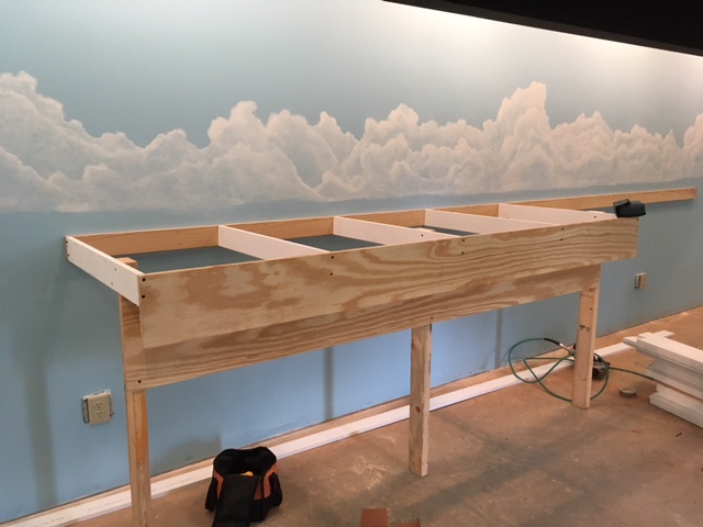 |
Bench height seems good. The 36 inch
front-to-back dimension is a reach but I think workable. Access to the
wire mounting board is
pretty good if you are seated on a low bench or stool, but the top two
or three
inches are perhaps a bit hard to get to. I don't want to lower it,
because the duck under is already pretty low, so I plan to reviese the
wiring layout for the board so that wires in the top few positions
are wires with very few intermendiate connections like loconet,
signal cables and system grounds,
etc.
The only other change involves the height of the fascia. I have raised
it up 1 1/4 inches so that it will cover the edges of
the plywood/homasote layers of decking or roadbed. This will
necessitate making it 9 1/4 inches wide instead of the 8 inch width
pictured here. |
Basic Bench
Work Completed
4/18/2017
Watching professional carpenters work is a wonder. Two men did
this in a two days, and they did it better than I could
have done working
alone for many weeks. Below
are a few photos of the finished basic bench work.
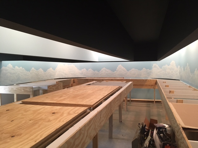 |
Looking east down the aisle between the
center and the north sections. The center setion is huge - 5 feet
wide and 22 feet long. I'll not lay track on this section until I have
pretty well finished the rest so I can use it as a work bench and
staging area for materials. Here we see some plywood ready for future
use. |
 |
Looking east down the aisle between the
center and the north sections. In the left foreground we can see one of
the two 5-foot-wide turn-around sections by the door. Track access in
tunnels on these large sections is going to be tricky. Also
construction
of the mountain in the difficult-to-reach center of the turn
around section will be a challenge, |
Now that all of the bench work is in place, I can
fully evaluate
its design
in detail.
In general, it looks very good indeed. However, I can see a few
potential
problem areas.
First, coming out a full, 36 inch from the backdrop wall was ambitious.
I knew this. With the bench in place, I now feel perhaps 32 to 34
inches
would have been better, but there are not many places where the track
is right up against the backdrop wall because I like to leave room for
force perspective near the backdrop and room for the scenery to make a
seamless transition from the 3 dimensional bench
to to the 2 dimensional backdrop. Also I am tall, so I do not think
this represents a real problem, just a little stretching when working
close to the backdrop wall. I feel that wider is better as long
as I can
reach everything without too much strain.
Second, and certainly a little more problematic, are the two 5 foot
wide turn-around sections of the bench by the door. This comes as no
surprise.
I wanted large radii for
the turnarounds, and I knew that the center of this area would be
difficult to reach, so I designed this section to accommodate a large
mountain with the track turn-around radii in a tunnel hugging the
outside
edges next to the
bench edge and next to the backdrop wall. With the sheet rock
cut-away in the backdrop wall beneath-the-mountain
and with a removable 5 foot side panel I
should have adequate access to all the
track in the tunnel from behind the backdrop walls and from the side
walls by the entrance.
At Fitzhugh there are three difficult-ro-reach turnouts (a crossover
and a depot
siding entrance) on the mainline next to the backdrop wall just
outside the tunnel, I plan to access these difficult-to-reach
turnouts from behind the backdrop either via a removable section of the
against-the-backdrop mountain silhouette framework that
will reveal a sheet
rock cutaway just behind these turnouts or via removable section on
mountain that will allow me to stand between the bench support cross
members right by these turnouts. I have not decided which is better,
and I may do both.
The construction of the central part of the
mountain itself will be a challenge. It is definitely in a
bench-top area I cannot reach. The
solution here,
I think either is to construct the large central section of the
mountain on
the
work bench and then poison the finished section on the layout and
tie it into the adjoining stationary parts of the
mountain, or if I do the removable section mention above, then this
will allow me to stand righ next to the mountain. Again I have not
decided which is best.
Last of all, seeing the massive bench in place reinforces my concerns
regarding access to the hidden yard beneath Altamont City. I have been
sensitive to this from the beginning and throughout the design stage.
Accordingly, I have paid close
attention to the design of hinged tops that will afford hidden
yard
access: one from behind the backdrop wall and one from the end of
the southern viewing aisle. I will build and evaluate these hinged lids
as soon as the roadbed for the hidden yard is in place, and should
there be any problems, I'll take whatever steps necessary to assure
good open access to all nine tracks in the hidden yard from one end to
the other, even if I have the redesign the terracing for city of
Altamont.
Taking Stock and Planning the Next Move
4-22-2017
Looking at this enormous bench is daunting indeed. I am beginning to
obsess about future problems and hard to reach areas, and this is not
good. I need to slow
down, and take things one at time. All of my potential problems,
whether they be real or just perceived, will be addressed in due time.
What is needed now is an initial plan of attack. I'll begin with a
task list in logical order with some distinct priorities.
First on the list will be a thorough cleanup. Dust down all the walls,
vacuum and sweep thoroughly, and mop the floor. Then I'll build some
small work benches in the corners of the behind-the-backdrop area and
some shelving and see to work lighting in this area. Once this is done.
I can move my tools and all my supplies and materials from my current
shop into the new space. Then I be ready to begin work on the
layout. I'll begin with the Fitzhugh section, the green power district,
90-1.
Getting Started
4/29/2017
Layout construction will begin section by section
beginning with section 90-1 (green) to the right of the door as
you come into the train room. This
will be the location of the town of Fitzhugh and Fitzhugh Mountain.
There are some hard to reach turnouts on the far side of the 5 foot by
5 foot turn around
section under Fitzhuhg mountain, and I want to begin here to perfect my
reach-through openings behind the
back drop wall and my removable panels. This will be
the
test case for accessing many of my difficult to reach spots.
The plan is this. I'll begin by installing the two prefabricated
turnout modules for the Fitzhugh section that I
built last summer and then constructing the plywood and homasote
graded roadbed that connects these modules. When this is done, I
will mount
and connect the Command Station/Booster, the PM42 Power Managers,
all five of the BDL168 occupancy sensor boards, the associated DS64, as
well as the 5 volt
and 12 volt DC power supplies, and then run aux power from the power
supply and track power
and grounds
from the DCS100 to the
power managers and from there to the occupancy sensors. Next I will
wire up the two prefabricated turnout modules I installed at Fitzhugh:
track power, 5 volt aux power for the dwarf signals, and the DS64
outputs.
I'll then test to insure I am
getting good, clean
digital signal
to the modules and that they successfully detect shorts
both when wired directly to the command station and when wired through
a power manager. I'll also test BDL168 occupancy sensing and the DS64
and Tortoise machines as well as all the dwarf signals. Then I will
be ready to begin laying track and wiring
blocks of track to connect these turnout modules modules at Fitzhugh.
More Detailed Topographical Planning
4-30-2017
While
I am building the roadbed, I am
thinking about the
surrounding topography. I already have a rough idea of where the town
goes, how it is laid out, and how the mountain will be contoured, but
as the roadbed and grades are completed, I begin to get a better feel
for the lay of the land. It is time to make a new, more detailed topo
drawing of the the Fitzhugh area so I can document any new ideas I
might get as I construct the roadbed grades, and then rough in the
basic
topographical framework before I move on. This
new drawing is an attempt
to establish the contour of the landscape that surrounds the track and
a more precise plan for terracing, retaining walls, rock outcroppings
and cliffs,
as well as roads and road-grades and bridges and tunnel entrances.
I began with a Xtrack CAD
print out of the section to be considered. This included all track
elevations and grade specifications.
Next I
amended the Master XCAD plan to reflect any changes in streets and
roads,
and I then lightly penciled in where I wanted large flat homasote
areas,
and terracing.
Then I considered the mountain that will go over open bench work beside
the industrial area, and penciled in a rough topo indicating the
location of any retaining walls, rock out cropping, forests, tunnel
entrances or rock cliffs etc.
One
again, what is created here is a guide for installation. This more
refined and thought-out plan varies considerably from the rough overall
topo I originally made. Still even a this stage, it is not intended to
be rigid, and as I progress, I will undoubtedly get ideas that
vary from the plan as I begin to see my terrain take shape in 3
dimensional space.
May 2017
Fitzhugh Section Roadbed Runners
and Terracing Complete
5-6-2017
Using my XCAD Track master rendering, I first very precisely
positioned the two completed and fully wired turnout modules, and I
then fashioned the connecting plywood/homasote roadbed runners paying
very carefully attention to uniformity of grades. The XCAD rending is
particularly useful in determining the height of all graded roadbed
supports, as it allows me to read the exact
elevation along a long grade at any point. Once these graded section
was installed, I used a long straight edge to check for any high or low
spots and made measurements all along the slope to ensure that the
grade percentage was just as specified and then adjusted the supports
as needed. When the runners were
completed, I fashioned terracing using 3/4 inch plywood supports for
the
homasote flats. I now have flat, terraced areas for the town of
Fitzhugh, for the industrial area, and as a base for my curved viaduct
stone
footings.
 |
The 30" radius 180 degree + loop
begins
the 1.7% grade from elevation +0" in the cut in the
background
of this
photo up to the depot and main town area at Elevation +2.25". The
diverging single track line along the backdrop wall continues up
to Altamont City at elevation +5". In the foreground we see the flat
area for the industrial park and siding at elevation 1.25" on the right
and the open bench work that will be covered by Fitzhugh Mountain,
which will rise to elevation +14". The back drop wall will be cut away
below the line where the mountain abuts the sheetrock to allow good
access to track in the tunnel. In the distance we can see the
two long flats for the town of Fitzhugh on either side of the lower +0
elevation mainline cut. |
 |
The mainline will run in a cut 2.25 "
below the town to allow for an auto road bridge connecting the two
sides of the
town of Fitzhugh. Near the center of this photo we see the roadbed and
grade for the diverging siding up to Fitzhugh Industrial Park. Above
and further back is the mainline crossover and the entrance to the
Fitzhugh depot siding. |
The next move is to install and power up the booster, the power
managers, the occupancy sensors, the DS64s, and
connect the associated loconet cables.
After that, I'll hook up the prefabricated modules. These are routes
not
blocks, so they will not be attached to an occupancy sensor. I will
then
pencil onto the homasote the
exact path of the track including all my easements. Then I'll
be ready to install cork roadbed, lay track, and wire it
up.
Rethinking the Use of the 12 volt Common Power Bus for Digitrax
Devices
5-9-2017
I had been thinking about tryng to power all my Digitrax devices
off the 12 volt unswitched power buss, but on second thought I
don't thing this is wise.
Digitrax does not recommend this, although their technical support
people say it will work if everything is wired up perfectly;
but they also say they will not support it. My experience
with Digitrax units is that
they are often sensitive to power issues, and looking on line,
the
consensus recommendation is not to use common power for Digitrax
devices except for like units.
I think it will be wiser, safer, and easier to troubleshoot to srick
with my original plan and power
only the DS64s off the common 12 volt bus, and use individual PS14 14
volt
300ma supplies - one for the two PM42s, one each for the BDL168s,
the SE8cs and the UP5s. Digitrax suggests that one can run two BDL168
units on one PS14, but I have had occasions where this caused a problem
when powering up the units, so each BDL168 will have its own individual
supply.
Wiring Begins
5-10-2017
I began by installing the DCS 100 Booster below the wire mounting
board, attaching it to a small pedestal on one of the bench legs
adjacent to the under-the-floor conduit to Fitzhugh. Next, I labeled
all
the mounting boards at ten foot intervals and mounted
all of my prefabricated PM42 and BDL168 boards on spacers 3/4"
above the mounting board in the locations specified on my XCAD Master
rendering. Next I
mounted the 12/5 volt DC power supply unit
attaching it to a bench leg beneath the wire mounting board in the center
of the section along the west wall below the City of Altamont. I
then ran the 16
AGW power buses
along the wire mounting board on
the Fitzhugh section and all along the south side of the center
section. I ran both
the 12volt
(brown+/white)] and the 5 volt (blue+/green)
(both switched and unswitched) again as specified on my XCAD
Track Master plan. Finally,
I connected track power to both PM42s and to
the BDL 168 at Fitzhugh using (red+/black-) 10AGW twisted pairs and
(green) 12AGW for ground, and I ran loconet from the booster to
all of these units. I then powered up the PM42s and the BDL168 at
Fitzhugh
using 2 individual "wall wart" PS14 power supplies and set the
PM42 board
addresses to 90 and 91
and the BDL board address to 95. I then tested these unit
insuring that the PM42 shut down this district when shorted while
continuing to power all other districts, and using the little 4 light
BDL168 tester module I insured that the BDL168 registed occupancy when
a load is attached across all of the outputs
 |
Here we see the bench fascia above, the
wire
mounting board below that, and the DCS100 Booster on its
pedistal. Mounted on spacers 3/4" above the mounting board, a PM42 unit
is wired to the booster flanked by an empty BDL168 interface. Notice
the 10AGW track power output
connection
from
the PM42 up and over the mounting board and then down into the conduit
in the floor leadng to the
BDL168 at Fitzhugh, Also notice the blue/green - brown/white 12/5 volt
bus bundle running along the bottom inch of the wire mounting board
connected to
the 12/5 volt power supply (both swithched and unswitched). |

|
Here we see a few DS64 units mounted above the wire
mounting
board and the Aux Power Supply - 12 volt (brown/white)
unswithed DC power to DS64s, 5 volt (blue/green) unswithced DC to Dwarf
Signals, 12 volt swithed DC to LED lighting chains, and switched 5 volt
DC to
individual LED layout lights. Relay switching is accomplished using a
DS64 output and zenor diode to make the polarity reversing output
into an ON/OFF output. The aux power distribution lines running
along the
bottom 1" of the wire mounting board can be clearly seen below the DS64
units. |
Hooking Up Prefabricated Turnout
Modules
5-11-2017
To get the undetected turnout modules operating, I
installed and labeled the associated DS64 units placing them on 3/4"
spacers out from the wire mounting board using my unswitched 12
volt power bus to power them, and I then programmed the
board addresses and the loconet addresses for these units according to
my
master plan and set Option Switch #1 to closed in order to operate
slow motion turnouts. I then
installed 12AGW (red+,black- common)
undetected track power bus lines connected directly to the PM42
district 95 output using the track power input
terminal on
the the BDL168 barrier strip at Fitzhugh as the source
and running them all along
the mounting board. The
last step was to connect the harness
wires from the prefab modules at Fitzhugh to this undetected track
power bus
(redA/blackB - 12 AGW) and to both the 12 volt (brown+/white-16AGW -
both
switched and unswitched)and the 5 volt (blue+/green - both unswitched)
power buses,
and to
connect all the DS64 output lines (brown/white - 20 AGW) to each
module's Tortoise leads.
 |
Underside of the undetected routes of
the Fitzhugh Crossovers
Prefabricated Turnout Module with the back of the wire mounting
board
below.
Connecting a prefabricated turnout module requires lines to power each
Tortoise Switch Machine, the connection of + and - 5 volt DC power for
dwarf signals (blue/green), and the A and B Rail track power cables
(red/black), which feed all of the module's track sections. |
I then did some testing, and found that the red function in one of my
dwarf signal LEDs did not work, one frog had no power, and the
dwarf signals on one turnout were wired backwards. Although I have
spent
a lot of time and effort trying to devise a system that did not require
me to work under the bench, I reluctantly crawled under to check things
out. As creaky as my old bones are, I was glad to get a chance to try
servicing my newly designed and installed Tortoise interfaces. It went
pretty well. At age 72, any work above my head in a confined space is
difficult for me, but visually things looked straight forward and
it was easy to see what was what - unlike the tangle of wire I
was
used to on the A&BR1. Most everything was more or
less accessible. There was one spot where access to the main barrier
block was blocked by a bench leg, but this leg could easily be
shortened if I ever need access to this block. Also any
blocks directly above the wire mounting board were a little more
difficult to survey and access, but this is not really a problem. So,
in
general, it
went well. The red LED failure was caused by stress on a wire harness
where it joined the Tortoise edge connector. The dead frog was also
caused by wire stress placed on the little copper ring tab which is the
solder point for connecting to the frog in an Atlas Code 55 turnout.
These turnouts look great, and they are, I am sure, well made;
nonetheless
they are delicate, and care should be taken at the time of installation
to ensure that there is not upward, downward or twisting stress placed
on the turnout or on any of its parts. The turnout must "float in
space" and lie flat and should not be subject any pressure from any
wires or track connected to it. Flexing or stressing the turnout can
cause failures in the internal connections to the frog, or to the point
rails, or to the closure rails. Finally reversing the polarity
leading to the frog throw switch in the Tortoise was simply matter of
swapping two wires on a barrier block. A piece of cake.
Hooking up a throttle directly to the DCS100, I ran some more tests,
and I
found that from the throttle I can now operate all ten
installed turnouts and run a loco across all sections the prefab
modules; and that all the
dwarf signals are lit a functioning properly. A
milestone!
Cork
Roadbed at Fitzhugh
5-19-2017
With the the two turnout modules at Fitzhugh wired up and tested, I
turned my attention to
laying track on the rest of the Fitzhugh section. I first penciled
onto the homasote the
exact path of the track including all my easements. Then I
used plain-old white glue to glue down my cork, taking care to follow
exactly the center line of the curves. I did a little shimming
here and there to eliminate any bumps where homosote joints were a
little
uneven using .020 and .030 sheet styrene.
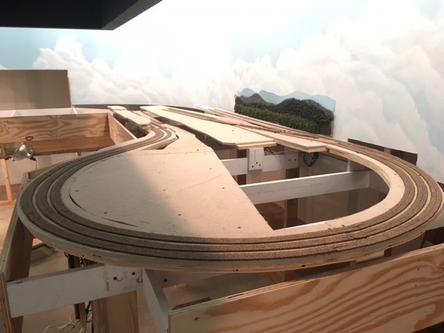 |
Cork raodbed on the 180 degree 1.7%
grade at Fitzhugh. Ready to lay track.
Note the shadow caused by the work lights blocked by in
the sofifit overhang. This will disappear when the flourescent
fixtures are installed as they will be placed much farther back on the
sofit.
|
Track Work at Fitzhugh
5-24-2017
With the cork in place, I began to lay track on the 180 degree curve
(the long single track to to the Altamont High Line block 95-9, and to
the two mainline tracks rising up and doubling back to the high ground
at Fitzhugh (blocks 95- and 95-13). I ran the 12AGW buses for the B
rail common and for the the three A rails along the wire
mounting board adjacent to the path of these three parallel sections,
and
using the track sections that I weathered earlier (except in the tunnel
where I used new unpainted track), I soldered a 20AGW solid copper
insulated dropper wire to the underside of the rails of each
section near the end of the rail and wired all the A rails back to the
BDL168 on the BDL168 barrier block and the B rails to the common coming
from section 95 on the PM42 also on the BDL168 barrier block. I then
wired my 16 AGW feeders to connect the droppers to the main buses
leaving an ample service loop at the dropper end. I
use a 3/16 inch drill for the dropper pass-through holes. This is
much larger than required for the dropper's tiny wire, but it allows
me a little slop for adjusting the exact positioning of the rail.
This could be a problem when I ballast the track, so I will go
back and close all of these holes with a tiny bit of modeling clay.
before I ballast. This will to prevent leakage of ballast onto
the floor, but still allow
for easy removal of the dropper should future service be required.
When all of the track in a section is thus laid, I test for electrical
continuity, proper shutdown of both the booster and the PM42, and
proper detection by the BDL168. I then glue the track down adjusting
the line using a straight edge and the alignment to precision as I go.
For the glue-down, I like to apply just
a spot of white glue under the track at about 4 inch intervals, adjust
the line while the glue is still tacky, and then tack it down with a
tiny wire nail which can be removed
when it is dry. This will hold the track well in place and still allow
for adjustments if needed until I ballast,
which of course will make everything rock solid.
Finally I will test my track work using trains of various lengths and
configurations to make sure that all the track is smooth, and that the
grades are not too steep anywhere along the incline. For me a grade is
too steep if an old Atlas RS unit working alone will not pull
twelve or thirteen 40 foot box cars or five or six 85 foot
passenger cars up
it at various speeds without much slippage. If they are properly
made, grades under 2% should easily pass this test.
 |
Here is the track laid on the three
parallel lines rising out of the cut at Fitzhugh, bending first to the
right and then back to to left into the long 180 degree curve. Notice
the short straight section in between the left and the right hand
curves. Most of this long curve will be in a tunnel so this is the
stretch of track a viewer will see east bound out of Fitzhugh. Despite
the fact that on the prototype these curves 2would be more gradual,
this
looks very prototypical to me. |
Labeling
5-26-2017
Now it is time to break out all of those color-coded sheets of
labels I so carefully prepared months ago during the planning stage. I
have already labeled all of
the digital devices that I have installed along with their distribution
panels, so it remains only to label my wiring. At this point all of the
labeling is in Power District #95, the green power district, so all of
these labels have a green background. My
convention is to place wire mounting board master labels at 10
foot intervals
along the board, and to individually label all wires that branch off
the wires on the wire mounting board both on the front and the back of
the board. I will also label all droppers on the underside of the
bench. This gives me a clear picture of what is going on on the face of
the wire mounting board and underneath the bench as well. In the case
of
blocks, A-Rail labels contain the name of the block and the block
address while B-Rail labels simply say "common" and the note the power
district number (in this case number 95); in the case of turnouts and
other
DS64 outputs, turnout labels contain the turnout address and anything
else gets the address and a further description as needed. I am yet to
devise a labeling convention for future 5 and 12 volt layout lighting,
but to be sure it will be similar.

|
Wire mounting board master label. These
labels are printed on plain white paper and then laminated with clear
packing tape. They are then stapled to the wire mounting board. Notice
the individual pass-through hole wire labels for 95 Common Rail-B and
for the
Fitzhugh Crossover undetected routes A-Rail (lower right). |
 |
The back of the wire mounting board
with individual wire labels. Plain paper labels affixed with white
glue. |
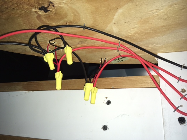 |
Dropper labels. Plain paper labels
affixed with white glue. |
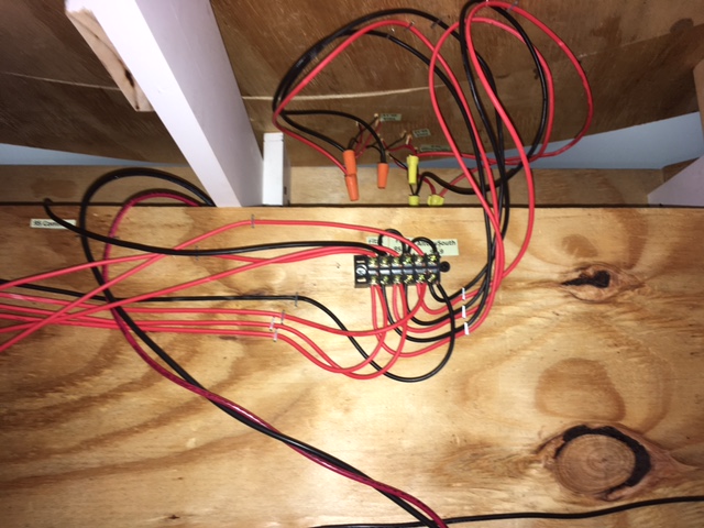 |
A track power distribution block on the back of the wire
mounting board with droppers above. The 10AGW twisted pair is the
track output of PM90 district 1 (90-1) on it way up from the
under-the-floor conduit to connect with BDL168 #95 (the Fitzhugh
district -green ). |
Evaluating the Wire Mounting Board
5-26-2017
The idea for the wire mounting board came to me while I was researching
the best way to wire track power over relatively long distances. There
has been a lot written about the wisdom of twisted pair wiring to
to void problems with inductance and crosstalk. I wanted to
get to the bottom of this. In the end, the best solution (and the
Digitrax recommended solution) was to twist the heavy wire (10AGW)
between the booster and the power managers and between the power
managers and the occupancy detector, and not to twist or bundle after
the occupancy sensors, but rather to run all the 12 AGW bus wires from
the occupancy sensors separately at least 1/2 inch apart.
This
naturally led me to the notion of a layout-wide mounting board to which
I could neatly create amnf label all of these spaced bus wire runs.
Then realized that if I mounted these mounting boards
horizontally attaching them to the bench legs instead of to the
underside of the bench, I could create a system that was much easier to
wire and service. Finally this notion of a wire mounting board also
seemed to go a long way toward avoiding the under-the-bench
tangles of wire that had characterized my previous layouts.
At first blush the wire mounting board seems to be the answer to all
three of these concerns. It keeps things neat, well labeled, and well
spaced and it is easy to access and work on. When I am seated on a low
bench, it is head high, very visible, and clearly accessible. I find
that it also has another advantage: the back side of the board is a
great place for organizing all of the under-the-bench wire distribution
in a neat, well labeled, horizontal and accessible presentation.
The only problems are the lowered crawl-under clearance, (it lowers
this by 8 inches, noticeable, but still quite workable), and the fact
that the top 1/3 on the board is behind the bench fascia board with
only 12 inches of clearance (a little awkward, but not a real problem
especailly since I have re-laid out the board keeping the least used
runs, like loconet, grounds, and my DS64 bundles etc. to the top of the
board which is overlapped by the fascia board).
Grade Easements
5-30-2017
With most of my grades under 2%, I probably do not need to construct
easements into or of out of my grades. I am about to lay track for the
siding at Fitzhugh which is a bit steeper, so a grade easement here is
probably a good idea. Unlike the rigorous methods used to calulate and
create track curve easements to ease trains into and out
of curves, for grade easements I usually simply do a little
graduated shimming using various thicknesses of sheet styrene for about
6 inches or so under the cork road bed to make a smooth change in
elevation up to or away from the steepness of the grade. This will
ensure that I do not experience coupler height issues that can cause
uncoupling at the point of an abrupt change in grade where one car
is on the flat and one car is in the grade.
One other note. I did experience one possible coupler issue when I ran
test trains to my long grades at Fitzhugh. This happened where I
had three parallel tracks ascending a 1.5% grade and a point where two
of these tracks began an approx 2% descent with no flat track in
between. I do not think I had ever encountered this before, but I
quickly realized that this was not a good practice because
it created a bit of a "hump." I installed shims to
create a short flat spot at the top and short easements from the up
grade and into the down
grade. This smoothed things out nicely, and it reminded me
why I like to use white glue to glue down cork roadbed: a sharp flat
blade and little moisture and it comes right up without tearing
anything up and can
be shimmed and glued right back in place without a mess.
Completing the Preliminary Work
at Fitzhugh
5-31-2017
Before I move on from the Fitzhugh section I want to finish the
mountain silhouettes against the backdrop wall, install the basic
homasote framework and the tunnel entrances for Fitzhugh mountain,
construct the removable hatch I have decided build to ensure really
good
access to the back side of the mountain and to the three
hard-to-reach-turnouts that are the crossover and the entrance to the
depot at Fitzhugh, and finally to cut away the sheetrock behind and
beneath the mountain to form
the under-the-mountain access from behind the backdrop wall. With the
addition of this removable hatch to access the three hard-to-reach
turnouts, there will be no need for the removable mountain silhouette
wall panel that I had contemplated earlier in this blog.
Once all of this is done, this section will be ready for scenery
building, but I'll delay that and move on to the mountain and curves
curves in the southeast corner of the room that will connect
to the south entrances to the hidden yard.
June 2017
Building the Basic Mountain Framework
6-2-2017
Part of Fitzhugh Mountain will be attached to a removable
hatch, so the first step here is to construct a good, sturdy base that
will serve as a hatch cover and as a base for the movable part of the
mountain. To do this, I measured and cut a piece of homasote to
fit
the space between the bench top cross members where I want to be able
to stand when the hatch is removed, and I then fashioned good solid
supports on the bench framework for this homasote cover to rest upon,
and I screwed a 1x4 to the bottom of
this homasote piece to prevent sagging. Homasote, if not well
supported, is
subject to rather sever sagging over time. That is why it is almost
always attached to plywood or braced with wood if it is used
alone to make any kind of span. I also fashioned a guide that will
allow me to fit the hatch back in exactly the same place each time it
is removed.
 |
Hatch cover and hatch cover supports. |
 |
Hatch cover in place. |
Next I defined the foot print of the mountain and gave some
consideration to how it will tie into the surrounding bench top
scenery.
In this case there are a few places where the mountains makes a smooth
transition in grade right down to bench level, a few places where there
will be retaining walls, and a few places where there will be rock
cliff faces. Marking the foot print and these transitional features on
the bench top will aid in designingt
should be any tunnel
portals. I think it is best to go ahead and construct and test tunnel
entrances first before I begin to construct the m
and cutting the homasote framework
that
will define the mountain. Included at this poinountain. To test
the portal clearances I simply run a train with some of my longest
cars.
 |
Sketching the mountain foot print. |
 |
Construct tunnel entrances first. I
make
a homasote mounting plate with openings slightly large than the
tunnel portal and screw the plate to a small wooden block that is
screwed down to the bench top. Before running my clearance test train,
I tack-glue my molded plaster portals to the homasote. (For all tunnel
portals, retaining walls, etc.I buy a single plastic prototype, and
from it I make a latex mold so I can cast clones in plaster of paris)
The double portal here is not wide
enough for my mainline-curve 1 1/2 inch track spacing,
so I'll
have to cut it, separate the two halves on the mounting board by about
half and inch and fill the gap with Sculptamold carved to match the
stone pattern. When it is painted and weathered, the patch is not
perceptible. |
Next, I design, cut, and attach (using sheet rock screws) a
homasote wall plate (a silhouette of the mountain at the place where
it meets the wall.) Then I cut away the sheet rock below to make the
reach-through opening, which allows access to
the track under the mountain from
behind the backdrop wall.
 |
Mountain wall plate. |

|
Mountain wall plate with sheet rock cut
away. |
Finally, I fashioned the main mountain homasote framework, support
ribs,
and the 3/4
inch plywood side fascia, and screw everything together using sheet
rock
screws. I take particular care to match exactly the frame silhouettes
where the part of the mountain that is on the hatch-cover abuts the
main
stationary mountain. This entire structure is pretty sturdy at this
point, and it will
get even more rigid when I come back later and put in more cross
members before applying the plastic screen covering. Once the screen is
covered with Sculptamold plaster and
the surface sets up, the mountain will be
extremely strong and rigid. I'll not do any further detail at this
point, especially in areas where I will force the perspective.
Effective forced perspective and the illusion of distance it can create
is best created working section by section and front to back when the
mountain surfaces are fashioned and covered with trees, foliage, and
scenery. So I'll leave any further detail until later.

|
Fitzhugh Mountain basic framework
complete. This is a really good technique for building large
topographical features. It is rigid, strong, very light weight, and
it affords quite a bit of flexibility creatively. Notice "bumps" in
the
contour about half way up the slope. These are for the rock
outcroppings and low stepped rock cliffs that will be installed at
the time of
the screen and Sculptamold application. Also I may go back and cut in
some flat
spots
somewhere on the upper slope to accommodate a few Z scale buildings.
I'll tend to this later when I work on the forced perspective. This is
just the basic framework and there will be a lot more to do on this
and other on mountains later on. I include the basic mountain frames on
my the preliminary work list in
order to
be sure that the access to all track underneath the mountain is
adiquate. The cut away sheetrock under the mountain allows me to easily
view and to reach all the track in the tunnel, and the hatch allows for
easy
service access to the three hard-to-reach turnouts next to the back
drop wall. |
Finishing up at Fitzhugh
6-3-2017
Over the next few days I'll finish the preliminary work at Fitzhugh. I
define preliminary work to include the following: all roadbed and
track, all track and signal wiring, all homasote/plywood flats for
structures and terracing, all bases for roads not on the flats, basic
frame work for all large mountains, all access openings, and finished
mountain silhouette flats attached to the backdrop wall.
To complete the Fitzhugh section, I
need only to connect
all control devices with permanent loconet cables, construct a
short section of highway roadbed between the town and the industrial
district, insert sleepers under a few rail joints where
sleepers were removed to install track droppers and rail joiners and
paint the rail joiners black, and
to build one more flat section of mountain silhouette for the west
section of of the south wall. Also I have two more dwarf signals to
install. These are already wired on the prefab module for the
crossovers at Fitzhugh, but they will be mounted on the bench top just
next to the modules. I will not install or wire any three
aspect signals at Fitzhugh until I dismantle the A&BR1 and free up
my SE8c control cards.
Preliminary Planning and Work on
the
Fitzhugh Curve Section
6-8-2017
With the preliminary work on the Fitzhugh section complete, I
can now move
on to the adjacent section, the Fitzhugh Curve. This section is a 90
degree curve of the double track main lines coming out of the hidden
yard and and double track main lines and a depot siding going back into
the hidden yard. There is also the single track
Altamont High Line and the single track west entrance to Altamont
Terminal and the
entire center section. These curves are mostly hidden underneath White
Side Mountain
that will stand between the town of Fitzhugh and the high ground for
the City of Altamont. Inside the mountain the High Line will cross over
both incoming and outgoing mainlines as well as over the entrance to
Altamont Terminal so good access to all track on the tunnel is
critical. I am counting on my sheet rock cut away underneath the
mountain to afford ample access from behind the backdrop wall.
In
addition all of the in-tunnel complexity in this section, the High
Line will
cross high above a mountain lake on a 24 inch curved bridge before
entering the mountain tunnel.
This lake and high bridge will will be a tricky piece of modeling
made all the more difficult by its hard-to-reach location. My plan is
to lay the track on a thin flat temporary 24 inch long curved piece of
wood so I can accurately and smoothly tie the track into the adjacent
curved trackage. Then I'll make a template that I can use to fashion
the bridge
curve to exactly match. Then on the bench, I'll build a a single large
module using the lake floor as a base. This module will contain a
backdrop wall photo and silhouette, the
cliffs that will border the lake forming one side of the
mountain, both the abutments, the footings for the supports for
the
bridge, and the bridge itself
 |
|
As before, I'll begin with a detailed track plan with grade details and
all track elevations noted and then I'll refine my topo plan and expand
it in more detailed sketches. As you can see, these sketches are very
rough at first, but they help to begin the evolutionary process of
designing something that fits the three dimensional space, is credibly
realistic, is buildable, and still affords good access to the track
underneath.
 |
My first rough three
dimensional sketch of White Side Mountain. |
 |
A more detailed
topo in
progress. |
This mountain is particularly difficult because of the extreme
elevation shift from the lake surface at -3/4 of an inch to +15 inches
at the summit in only about 2 feet. This is an extreme rise
of 210 feet in only 320 feet. On the sketch I have indicated the
rough location of sheared rock cliffs with little circles. Sheared rock
face cliffs with the strata exposed work well for low cliffs, say 10 to
20 feet high. Higher than this they often begin to loose credibility,
so in the steepest place on the west shore of the lake I'll create a
smooth granite expanse like one sees in the high Smokey Mountains.
 |
Some low sheared rock face cliffs on my
A&BR1 constructed using Sculptamold and pieces cut from a foam cast
Isle Labs multi-scale embankment. This is how I'll gradually step
up to the summit on longer the
Altamont City side of the mountain. |
 |
Quite often, before I build a bit of
scenery, I go on line and use my search engine to find photos to guide
and inspire me. These photos are useful in the planning stage for ideas
and in the building stage to supply guides for shaping and painting
etc. Here are some high smooth rock cliffs on the real White Side
Mountain near
Highlands, NC. This is the way I'll bring the mountain abruptly down
to the lake on the short side near Fitzhugh using smooth Sculptamold
cut here and there to create the diagonal and vertical fissures seen in
this photo. When painted to look like this and adorned with a little
clump foliage, this should look great on the A&BR2. |
I'll begin by installing, wiring, and testing the two prefabricated
modules that contain the turnouts for the west Fitzhugh depot entrance
and crossover and for the hidden yard's four south siding entrances.
Then
I'll build the homasote and plywood roadbed, leaving a gap where I want
the bridge to be. After carefully checking all of my elevations, I'll
glue down the cork road bed and lay, wire, and test the track, with a
temporary template support for the
track on the bridge for now. Then I will turn my attention to roughing
in the mountain's basic framework, cutting away the sheet rock for
access, and building the rough framework for lake module. Finally, I'll
build and install the bridge kit with its footings and abutments.
Track Work at Fitzhugh Curve Complete
6-15-2017
I have been working on the roadbed runners and the track work on the
Fitzhugh Curve Section. All the track is now installed, wired, and
tested, and yesterday I finished gluing it down. Most of this track
work will be underneath White Side Mountain, so I am using un-weathered
flex track sections right out of the box. This is the largest mountain
on
the layout, whose against-the-backdrop outline can be seen in the below
photo. As you can see, the sheet rock cutaway gives me excellent access
to all track in the tunnel. The next moves will be to install all the
tunnel portals, to rough in the basic homasote frame work of mountain
and for the lake bed, and finally to build the bridge and complete the
track laying on the overpass.
|
Here is the completed track work for
the Fitzhugh curve and the against-the-backdrop homasote silhouette and
sheet rock cutaway. On the right side of the mountain will be steep,
smooth rock cliffs and the lake below, and on the left, the mountain's
gradual slope
will terminate into the wooden form that defines the three tiered
terracing at Altamont City.The overpass and raised roadbed is for the
Altamont High Line. Track will not be laid here until the bridge
is complete. |
Finishing Up at the Fitzhugh
Curve - Mountain Framework, the Lake, and the Curved Bridge
6-20-2017
Below is a photo of the preliminary mountain framework for White
Side Mountain at the Fitzhugh Curve. As before at Fitzhugh Mountain, I
have only tried to rough in enough to indicate the mountain's basic
shape and its foot print and the location of all tunnel portals.
In this case I have also cut a few homasote forms to suggest where the
smooth rock faces will be. There will be a lot more added to this
framework later.
 |
Here is the basic mountain frame for
White Side Mountain. Notice that the ample sheet rock cutaway gives
excellent access to all track in the tunnels. Also notice the white
.040 sheet styrene strip that will serve as a template for the curved
bridge across the lake. Although it is not clear in this photo, the
styrene strip is a perfect 31 inch radius (outside dimension) and
exactly the length of the Micro Engineering Tall Steel Viaduct bridge
kit span (24 inches). This
track-tie-width strip will aid in the placement of the abutments, and
in the construction of the bridge it self. |
 |
View of White Side Mountain showing the entrances to the
sidings in the hidden yard and the crossover and entrance to the
Fitzhugh depot siding. |
The next move is to complete and install the Micro Engineering Tall
Steel Viaduct bridge, the bridge
abutments, the temporary footings, and the track using the white
styrene
template shown above as a guide. Then I'll build the last section of
backdrop wall mountain silhouettes, leaving room at the bottom
for a 2 dimensional representation of the far surface and shore
of the
lake. Later, when I create the scenery detail for this scene, I'll
install the styrene sheet for the lake surface and apply the basic lake
color
to that surface and to the far surface of the lake on
backdrop, and then work on the effects
needed to create the water's surface and its gloss. At that time I'll
add the finished footings, the lake shore detail, and also endeavor to
seamlessly marry the 3 dimensional lake surface to
the 2 dimensional distant lake surface of the back drop wall.
 |
The finished bridge ready for track
laying with supports on temporary footings, abutments installed, the
roughed-in lake, and the backdrop panel for
far shoreline and mountain silhouette. |
Beginning Work on the Hidden
Yard
6-22-2017
The hidden yard is simple affair: the four mainline tracks each with
its own long siding. This allows me to park trains out of sight for a
period of time during long automated schedule sequences, and then
to have them reappear at a later time. I have already installed all of
the yard entrances on the south side (the Fitzhugh side). So I have
only to install the prefab module with the four north side entrance
turnouts
and lay the track in
between the north and south entrances and wire everything up. Seven of
the eight blocks in between entrances are part of the Fitzhugh District
95, and one is part of Altamont Terminal District 96. Also the
north entrance turnouts are routes, which are part of the Altamont Yard
Power District 97. So I will have to wire up two more power districts
and two
more BDL168s.
I'll begin by installing the 10 AGW lines from the PM42s to all the
remaining
BDL168s. Next I'll install
the prefab module containing the north side hidden yard
entrance turnouts, run
the detected and undetected main track bus
wires and the turnout power wires to the wire
mounting board and connect them to correct the BDL168s and a DS64
respectively. Then
I'll lay, glue down, and wire the track in
between. This will complete all the track laying and wiring for power
the
Fitzhugh Power District #95.
 |
Hidden yard track laying
completed.Since all of this trackage is hidden from view, I have used
un-weathered track right out of the the box, and I have not patched
any of the spaces where ties have been removed in order to make joints
or dropper connections. Also since I raised the elevation of the the
depot and surrounding buildings at Fitzhugh, I
have had to create a grade up to this level at 2.25 inches above 0
bench
level. On the Fitzhugh Mountain side, this was accomplished by simply
having the two main line tracks ascend the grade along side of the
Altamont High Line and then split off to level at elevation 2.25.
On the
Fitzhugh Curve side, the long grade is part of the first four tracks on
the curve and in
the hidden yard. This means I had to split the two prefab modules
lengthwise so one could be flat and one on a grade. |
 |
Fitzhugh Power
District #95: a section of the wire mounting board completed below the
approach to Fitzhugh Mountain. I am very happy with the mounting board
scheme. Not only does it keep all of my wiring accessible,
visible, and neat, it minimizes the chances of cross-talk and
impedance problems by keeping all 12AGW post-occupancy sensor buses
parallel and at least 1/2 inch apart. Power feeds to the occupancy
sensors from the power managers and from the booster to the power
managers are 10AGW twisted pair. The "XX" mark on the bench leg is to
indicate the location of an AC outlet. there will be 12 of these around
the layout attached to bench legs and all switched on/off on the master
control panel, which will be located by the computer console, so a
single switch will power up/down the entire layout. This master panel
will also have the HVAC thermostat control and the servo controlled
dimmers for the room lights. |
Framing and Installing the Hinged
Covers
for the Hidden Yard
6-30-2017
Now that the track work for hidden yard is complete and before I go on
to the Altamont Curve section of the layout, I want to frame and
install the hinged cover that will cover the hidden yard and support
the City of Altamont. This could wait until later, but I will do it now
because I want to be sure this cover, which opens up and away for the
backdrop wall, will allow ample access to all of the track and turnouts
in the hidden yard. The adequacy of this hinged cover, will help me to
decide how to handle access to the northern portion of the hidden yard,
which does not have access from behind the backdrop wall. I have
questions as to how much of this end of the yard I want to cover with a
second hinged cover that opens the other way, and whether or not I can
create an opening wide enough to stand in middle of the bench work when
the cover is open in order to access the four turnouts that are the
north entrances to the hidden yard sidings. The configuration of this
second
hinged cover will in turn effect the topography of Altamont City and
the mountain at
Altamont Curve, which I now plan to make small enough so that all of
the curved track between the west and the north bench will pass
through in cuts, not tunnels,
and therefore be easily accessible from the train room aisle without a
hatch. In addition, I want to get a feel for the height of the hinged
covers, because I want to make the opening in the sheet rock wall a
bit smaller (lower) so the mountains in the backdrop silhouette behind
the city can be a bit lower and therefore line up better with the
horizon I have already established behind the Fitzhugh Section. The
drawings for these hinged covers and a discussion of this plan can be
found in the 3-25-2017 entry of this blog.
 |
Hidden Yard Hinged Cover#1 -Closed
This cover is the framework for the terracing in the City of
Altamont - 3 levels, each
1 1/2 inches above the next. The main streets will run latterly and
parallel. I'll notch the cross members to accomodate perpendicular
graded cross
streets connecting the main streets on all levels. |
 |
Hidden Yard Hinged Cove#1 - Open Access
to the hidden yards is excellent from behind the backdrop wall - so
much so that I will be able to add about 6 inches of sheet rock to the
lower edge of the backdrop behind this section. This will make the
horizon behind this section line up better with the horizon behind
the Fitzhugh and the Altamont Yard sections. I'll delay adding the tree
line and mountain silhouettes until I lower the sheet rock opening. The
transition here from 3 dimensional foreground to flat backdrop will be
involved with lots of paste on photos, so it is best to delay the
addition of the silhouetts
unitl I add streets and buildings on the back terrace. |
 |
Hidden Yard Hinged Cover#2 - Closed This cover opens
the other way, that is to say, it hinges on the backdrop wall and
allows access to the track and turnouts in the North end of the hidden
yard from the bench aisle. There is no terracing here, and I will just
rough in the flat areas and a suggstion of the mountain shapes for now.
My plan includes a small area of
high ground in the center of the City of Altamont. with a Cathedral
atop. North of that, I'll build rolling hills for a
high-end residential area. At the north end of this cover, I'll
transition into the mountain at the Altamont Curve and two large
cuts
where the mainlines will run. See the following sketch. |
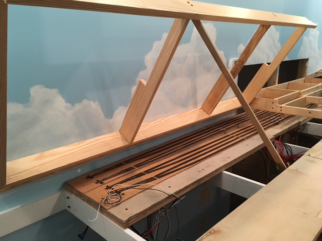 |
With this cover fully open and the hatch removed, I can stand
in between the bench
cross members with excellent access to the track and turnouts at
this end of the hidden yard. |
July 2017
Topographical Planning for Hinged Cover #2 and the Mountain at the
Altamont Curve
7-3-2017
The preliminary sketch pictured below is very rough, but it is enough
to give me an idea of the general lay of the land so I can
rough in a few basic forms. This topo suggests the shape of the
mountain that will cover the second hinged cover and extend down into
the terminal area, the location of the hatch for the stand-in access,
the location of the cathedral, cemetery, houses, Z scale houses, and
the cut for the Altamont Highline and a parallel roadway. It also
suggest how I will handle the viaduct, the bridges, and the large cuts
on the
Altamont Curve as well as the transition from backdrop silhouette on
the
hinged cover to 3 dimensional mountain on the curve.
 |
The general topography here calls for
two mountains, one peaking in front of the mountain
silhouette, which is set a few inches out from the backdrop wall so the
hinged cover will have room to open and one
peaking against the curved backdrop wall. There are ridge-like fingers
extending
down into the terminal area on the center section of the layout, and
down and around the Altamont curve to form the cuts. There is
a High
Line viaduct and a bridge and two roadway bridges and two sets of
tunnel portals.
The stand-in access opening will be covered by a one foot by four foot
removable hatch. |
 |
Here I have roughed in the high ground for the cathedral
(back far right), the summit line of the ridge (back right
center) and rolling hills with falt spaces where the Z scale painted
ladies (Victorian mansions will be (back left). That is all I will do
for now. I plan
to line the tracks and the roadway that will run along the 8 inch-wide
lateral plywood board in the foreground with old houses facing the
railroad. This was the
popular style around turn of the twentieth century in so many Southern
towns. I'll build these
features later and create the illusion of depth working in small
sections front to back. Also I want to wait to install the flat
mountain sihouettes on the bck drop wall unit I install the silhouettes
on the Altamont Curve so I can make a good transition between
this section and the
next. |
Track Laying, Bridges, and Rough
Topography on the Altamont Curve
7-7-2017
The Altamont Curve's four mainline tracks will connect the Hidden Yard
under the City of Altamont and environs with the Altamont Yard section
of the layout with two mainline tracks passing north of the yard and
two passing to the south of the yard.
I'll begin by installing, wiring, and testing the two prefabricated
turnout modules that will provide access to the yard: one from the
north and one from the south. These modules tie into the four mainline
tracks on the
Altamont Curve. Then I'll cut and install the homasote and plywood
roadbed, glue down the cork; lay, wire, glue down track on the curve
itself; and test the
whole thing. Next, I'll turn my attention to roughing in the
mountain that will be against the curved backdrop wall and the
remaining
mountain forms that will form the walls of the two cuts. The trick here
is to imagine the mountain before the railroad was built and then
imagine what, in the way of cut and fill, had to be done to make the
smooth rights of way. Then, I'll build the mountain silhouettes
against the curved wall and make the transition into the slightly
higher horizon silhouettes behind the hillside above the Hidden Yard.
I'll wait the extend the silhouette behind the
downtown City of Altamont unitl I begin work of the city scenery
because these silhouette will require a number paste-on photographs on
the backdrop behind the city buildings. Finally I'll
install the roadbed for this side of the Altamont High Line and
construct and install all railroad bridges, roadways and roadway
bridges.
 |
Here are the prefabricated turnout
modules installed
and wired to buses on the mounting board and the plywood/homasote
roadbed on the curve completed. Since all the track is
accessed from above, and since the mountain here consists
of only the narrow high ground and small cut away sections of
the ridge, and since there are many flat yard ladder spurs on this
section, I
decided not to use any open bench work here. Rather than build runners,
I covered the entire section with plywood and homasote the same way I
will do on the adjoining yard section. |
 |
Here is the rack laid and wired on the
Altamont Curve. For whatever reason, in my planning I neglected to
assign blocks to all four mainline tracks on the Altamont Curve. These
are far too long to function well as routes, so I had to steal
occupancy sensor resources from the yard ladder and change the
TrainController switchboard accordingly. I am now left with four more
undetected ladder spurs in Altamont Yard. I may add an additional
BDL168,
or
I may try some other brand of detection circuit. I have been interested
in the RR Cirkits line of products for some time. |
 |
Mountain background silhouettes and
mountain forms roughed in
to form the cuts. The central ridge between the two cuts will be a
rough, forested, rocky slope with steep rock walls dropping straight
down to track-side in the cut itself. Notice the narrow curved roadbed
supported by two plywood plates for the bridge abutments. This narrow
curved strip will will support the track on the rocky crag
between the two bridges.
|
 |
Here are the completed backdrop silhouettes, and the roughed
in bridges, bridge abutments, and temporary bridge support footings for
the Altamont
High Line as it crosses the yard ladder spurs and the two mainline
track pairs
of the Altamont
Curve and the South entrance to Altamont Terminal. Here two long curved
Micro Engineering Tall Steel Viaducts are
used. Instead of making one long viaduct, I opted to
have a rock formation cut from the spine of the descending mountain
ridge
separate the two viaducts. This way the High Line curve begins and ends
with a viaduct at either end with a short section of rocky
mountain in the middle. I had to kitbash both of the 24 inch-long
viaducts to make an exact fit. I've shortened the north span on the
north bridge
and lengthened the center span on the south bridge. |
Track Laying on the Altamont High Line
8-1-2007
Now that the multiple viaducts for the High Line at Altamont Curve and
at Fitzhugh Curve are complete and in place, I can lay track on these
bridges and on
the rest of the High Line and thus connect the two viaducts and the two
long High Line grades. I have added a second depot siding with room for
a platform on the High Line at Altamont City. This is part of a
redesign of Altamont Terminal that I am currently contemplating. The
idea
is to construct a multi-level terminal complex servicing the 6
north-south oriented spurs underneath as planned and also servicing the
two east-west oriented sidings above. I'll steal two positions on DS-64
#59 that I had planned to use for crossing gates to power the two
turnouts for the additional siding, and I'll rob a detection
section from the Altamont Terminal ladder. I can easily deal with the
crossing gates at Altamont City and the ladder block detection by
adding more components later on.
Updating the Track Plan
8-4-2017
The track plan and switchboard below reflect some recent changes
including the addition of the second Altamont High Line Siding and the
removal of the two crossovers connecting the entrances to the loop at
Altamont Terminal.I don't know what I was thinking when I added these
crossovers. They presented a serious problem vis a vis auto reversing
section designations, and they are totally superfluous since the AT
Traverse/98-5 auto reversing crossover track accomplishes the same
thing. The new plan also reflects the
robbing of the four Altamont Yard Ladder blocks for use on the Altamont
Curve, and an additional BDL168 (#100 - power district 91-3 [orange])
to service the Yard ladder, the terminal Yard ladder, the streetcar
line, and a few heretofore undetected spurs.
 |

|
Shutting Down the A&BR1, Installing Salvaged Components and
Preparing for Comprehensive Testing on the A&BR2
8-6-2017 through 8-25-2017
The time has finally come to begin dismantling the A&BR1. I
plan to leave it all in place and simply rob and refurbish what I need
for
the new layout as I go forward. The first things I'll need are the
fluorescent lights and dimmer, all of the trains, all of the BDL168s,
the PM42s, some of the DS-64s, the HUE bridge and WIFI repeater, the
surround sound card and the speakers, and the RR Cirkits serial
interface for the computer.
Once I install the salvaged Digitrax PM42s and BDL168s and finish
wiring
the
High Line and the Hidden Yard and High Line sidings' Tortoise
machines and associated DS64s on the West side of the layout,
I'll have about one
third of the track laying completed for the peripheral mainlines on the
A&BR2. At this point it will be time to begin more extensive
testing of the track, turnouts, and the new TrainController switchboard
and setup. To do this I need to hook up the computer and run all my
trains using series of comprehensive looped automated schedules that
will run all trains over all of the newly-laid track and turnouts both
forward and backward
at
various speeds. This will involve a thorough cleaning of all new track
and turnouts, re-profiling all my locos, and programming brake and stop
markers and speed settings into all completed blocks. I also plan to
put new wheel sets on all of my cars at some point.
After the testing, I plan to install and test the 11 old fluorescent
lights along with 10 new ones, the dimmer and its associated servo
control card, and the WIFI repeater and the bridge for the HUE
lights. Then
I'll install the surround sound system and program the sound for the
blocks that I have installed to date. I will also rob the signal cards
from the A&BR1 and install one on the wire mounting board just
south
of the
Fitzhugh Curve. This card will control the signals at Fitzhugh, on the
Altamont High Line,and eventually on the entire Altamont Terminal
center section
of the layout. I'll then install signal masts at Fitzhugh and on
the High Line and fit them with targets, electrical junction boxes,
ladders, and service platforms (more of this later.)
This is a tall order, and it will take some time; but when I am done, I
can return to laying
track knowing that all systems are working as planned; and it will then
be easier to thoroughly set up and test each new section as I go. There
will not
be much to discuss while I install the rest of the BDL 168s and
the other PM42, finish up the track wiring on the High Line,
install Tortoise machines, and clean all
the track, but I will note my daily
progress below as I go.
8-6-2017: Installed Tortoise interfaces for the south entrances to the
High line sidings (turnouts #113 & 117.) Installed
and set up BDL168#97 and finished bus and feeder wiring on the
High Line except for the 2 north siding entracne turnouts.
8-7-2017:
Began dismantling the A&BR1: removed the computer interface
including the Loco Buffer, the RR & Co license dongle, the
surround sound interface and all the speakers, the florescent lighting
dimmer interface including the servo motors with clevises and the servo
control card, 4 BDL168 Occupany Sensors, 1 SEc8 Signal Card, 1 PM42
Power
Manager, a handful of Digitrax "wallwart" Power supplies,
and 2 custom layout lighting relay control circuit boards. On the
A&BR2, I installed
and set up PM42 #91 and BDL168 # 96, and
I successfully tested the Hue WIFI repeater and HUE lighting bridge
and a HUE light in the new train room.
8-8-2017: Removed
4 more Tortoise machines from the A&BR1 and installed and tested
them on the 4 north hidden yard entrances
(#100,101,111,112) which are connected to DS64#55,
8-9-2017: Removed 5 more Tortoise machines and all Digitrax Signal
Masts from the South side of the A&BR1, and
on the A&BR2 I installed and set up DS64#65 to which I connected to
the Tortoise feeds from the 4 Tortoise interfaces for turnouts
at the 4 south entrances to the Hidden Yard sidings (#s 514,515, 517
& 518). Installed
and tested 1 Tortoise machine at
the south entrances to the
Hidden Yard siding (#518.)
Began track cleaning.
8-12-2017:
I have been away for a few days, so no progress the layout, but I have
had some time to prepare TrainController for the up coming testing. I
have entered stop markers in both directions in all blocks placing them
either 50 or 30 inches into each block. I have also entered brake
markers 0 inches into each block in both direction with either 50 or 30
inch ramps. I'll
go back after I hook up the computer and measure each block and place
all these markers appropriately near the ends of each block. I
have also created 20 schedules and linked them together into
long schedule sequence that will run test trains over all installed
track and turnouts. I have left the speed default unchanged, so
initially I can run trains at their max speed up to an unrestricted 80
mph. or I can run at a restricted
25 mph. I can of course run trans at any speed up 80 mph simply by
limiting the max speed for each locomotive in TrainController.
8-13-2017: Installed
and tested 3 the remaining Tortoise machines at
the south entrances to the
Hidden Yard siding (#514,
516 & 517.)
Installed and tested Tortoise
Interfaces for the 2 turnouts (#114 and 116) at the north entrances to
the High Line sidings. Installed and tested 2 Tortoise machines on the
turnouts at the north entrances to the sidings on the Altamont High
Line (#s 114 & 116) Continued track cleaning.
8-14-2017:
Installed
and tested 2 Tortoise machines at the south entrance to the Altamont
High Line sidings (#s 113 & 117).
Labeled all the Tortoise installations of the last few days and glued
down the track on the center section and the sidings on the Altamont
High Line.
8-15-2-17: Removed all loconet cables from the A&BR1 and removed
the
UP5 unit. In preparation for hooking up the computer, I
constructed a rough, temporary control panel and a temporary laptop
shelf and mounted the Master AC layout power switch on the temporary
control panel. I then installed UP5#1 in the bench fascia above the
temp panel and installed and tested permanent loconet cables from Track
A output on the buffer to all
installed components at Fitzhugh, the West bench. I temporarily mounted
the RR Cirkits LocoBuffer beside
the temp laptop bench, ran a loco net cable to the addition jacks on
nearby UP5 #1 and a serial cable one of the ports on the computer. I
was using the same laptop that I use to control the A&BR1, so the
LocoBuffer driver is already setup. I opened the TrainController
software and used the switchboard to first test operate all of the
installed turnouts, and then I opened a train window and ran my test
loco around a little using first a train window throttle control and
then using one of my schedules. The train runs the schedule OK, but the
brake and stop markers at the end did not
seem to work. Also BDL168 #95 at the end of the chain did not work in
the Track A chain, although it worked fine when connect directly to the
buffer. This turned out to be a bad loconet cable connecting this
BDL168 at the end of the chain, although the cable tested "good" using
the 4 light tester.
8-16-2017: Stop markers now work after setting all the brake markers to
a
non-zero position and adjusting the ramps. I ran temporary loconet
cables from Track B output
on the buffer to BDL168 # 97 on the south bench and on DS64 #65 on the
Altamont Curve. BDL168
#97 did not work, but it worked OK when the Track A output chain was
disconnected. I swapped out the temporary cables to no avail. Then
started removing devises from the end of the TrackA chain and found
that if I bypassed the newly installed UP5 unit everything seemed to
work fine. Either the UP5 is corrupting loconet or the BDL168 #65 is
bad. I'll
swap them both out tomorrow.
8-17-2017: Replaced the UP5 and everything works fine. I'll return it
to Digitrax under warranty. I moved two long freight trains and two
passenger trains from the A&BR1 to the A&BR2. I plan to
re-profile these units and replace all wheel sets at some point, but
for now they are OK for testing purposes. I spent the day running short
schedules and tweaking and cleaning any track work or turnouts that
caused jitter or bumps or unwanted elevation changes. I repaired one
turnout that did not work (I had shorted a wire with a staple), and one
frog that was wired backwards. Otherwise things worked well, except
these trains need wheel and coupler maintenance in the worst way.
8-18-2017: Continued with track cleaning, and programed a few longer
schedules forward an backward for all four trains. I also tested the
sound in stereo on my
laptop in preparation for installing the surround system, and I moved
all my HUE bulbs and installed and tested them in the new train room. I
spent the afternoon evaluating the new track and turnouts, watching for
derailments, bumps, hiccups etc. and making adjustments to track,
turnouts, couplers, wheels and trucks. I think I'll go to all Fox
Valley 36" .540 axle metal wheels for all passenger cars on the two
trains that I have retrofitted with MicroTrains 4 wheel 1017 trucks. So
I change out the out plastic wheels on one passenger train and order
more Fox Valley wheels for the other. As to freight cars, I have such a
mixed
bag, it is difficult to standardize. I think I'll just switch out all
wheels and some trucks for whatever works best. By the end of the
afternoon, everything running pretty smoothly, testing 60 to 70 mph
forward schedules and 25 mph on backwards schedules.
8-19-2017: I changed out the old plastic wheels on my passenger train
running the old Rivorosi Heavyweight cars, installing new MicroTrains
Standard 33" plastic wheel sets into the already-installed MicroTrains
1018 six wheel trucks, finished cleaning all the newly installed track,
and spent a few more hours testing and tweaking the track and turnouts.
With a few exceptions, most of the problems I encountered were problems
with wheels, trucks, or couplers and not problems with the new
track.
8-20-2017: Ordered speaker wire, installed the sound box and
constructed speaker mounting shelves and installed sound system
terminal blocks by the sound box and beside each speaker shelf . I
think I mention before this is a very inexpensive system (Encore
ENMAB-8CM 7.1 Channel UBS Audio Box - $30, 4 pairs of Gear Head
SP2600ACB 2.0 Desktop Speakers @ $16/pair). It really sounds good, and
it is ideal for this application because it sounds the most realistic
for the tiny N Scale trains when set at pretty low levels. A big, loud,
high quality, surround system would be too much, and would cause audio
confusion in the large room when multiple trains are in operation. I
have my Railroad and Co. 4D sound system set to simultaneously play the
sound of up to five trains at once, and when set at low levels this
surround system outputs a very specific spacial location for the sound
of each train.
 |
Mounted just below the wire mounting
board and just above the main layout power switch, the Surround Sound
Box is connect to the nearby computer via a USB cable. The 4 output
jacks feed 4 amplifier/speaker pairs (L,/R, C/SW,
RS/LS, & LR/
RR). Each jack runs to a terminal distribution block where the audio
feed pairs are connected to the speaker/amplifiers using regular 2 wire
speaker cable. The grounds are all bused together. This way all the
amplifiers can be
grounded to a single ground bus which goes out to both side of the
room. |
 |
Here is a little Gear Head Speaker/Amplifier ready for
speaker wire installation under the bench
on its cork padded
mount with its terminal block. This is a righthad speaker containing
the little amplifier, so it has both an input from the sound box and an
output to the left speaker as well as a power cord. |
8-21-2017:
Finished installing speakers mounts, speakers, speaker terminal
blocks and speaker ground bus. Tested this installation by hooking up
rear speaker pair and found a balance problem (right speaker louder
than left). Changed out chords to no avail. I spent the rest of the
afternoon troubleshooting wiring, software, hardware, computer settings
- everything. At times the problem was intermittent. A real bear!
Mystifying! Finally I found the culprit. Two of the four wires that
connect between the speaker jack output of the sound box and the newly
installed barrier block were damaged in the same way - damaged by
screwing them in too tightly to the barrier block. So swapping out the
wires during troubleshooting did not always prove anything at all.
Anyway, I learned that these tiny braided wires are very fragile and
have to have a short piece of bus wire soldered to their tips before
securing them to the barrier block. I'll fix it tomorrow.
8-22-2017: My speaker wire came yesterday, so I began hooking up
speakers, and corrected the fragile wire/barrier block problem by
soldering short pieces of 22 agw bus wire to the ends of each of the
small speaker wires that come ount of the speakers. A short piece of
shrink wrap covers the solder joint, and now I can insert the solid
piece of wire into the barrier clock and screw it down tight without
damaging the almost microscopic strands of wire. On the other side of
the block the new speaker wire is plenty robust to endure the pressure
of the screw-downs. The under-the-floor conduit served me well in
running speaker wire and speaker grounds, and I now have the left and
right surround speakers and the left and right rear speaker
working. I spent a little time tweaking the system and adjusting
sound box outputs and speaker volumes and setting up the sound tracking
in the blocks of one of my test schedules. In the large train room the
4D Sound really works great, and the tracking
feature
is exceptionally
effective when things are set up just right.
8-23-2017 I made the
second pull of speaker wire and ground wire through the conduit under
the slab to the south
bench and completed, tweaked, and tested the entire surround sound
installation using its its own diagnostic software as well as
TrainController. Then I began
a complete train room clean up. The electrician will
be here soon to install
the florescent fixtures (10 new ones and 11
salvaged from the A&BR1), so I need to be sure none of my
stuff is in his way and that all of the open bench-top areas are
clear. This installation might be difficult in the areas above the
sections where I have already laid track. I hope I have not made a
mistake by delaying this installation of these fixtures, but I had to
wait until the old
layout was decommissioned before I could rob the 11
fixtures and the dimmer from the old train room.
8-24-2017: Built a shelf for the center speaker, which is a bit larger
than the Gear Head speakers use everywhere else. Built a little
fold-down shelf next to the future computer desk with a programming
track attached and wired back to the DCS 100.
 |
Train room after clean up.
|
 |
This little restaurant table-busing
cart is a must, a consistent place to sort and store and have
ready-at-hand
glues, screws, nails, shims, clamps, work lights, wire and all sorts of
building materials, as wells as extension cords, power tools, and spray
paints and solvents on the lower shelves.The tool boxes on the floor
behind also help
keep things in order. The small one on top with the yellow handle is
for
detailed modeling tools;
the medium sized yellow one is for tools and materials used in
electrical
work. The gray metal tool box contains my carpentry and mechanical
tools,the large yellow plastic tool box is for modeling and
drawing
materials, and the large gray plastic tool box is my paint box. A place
for
everything and everything
in its place.
|
8-25-2017:
The period of tweaking and comprehensive testing is almost over and it
is nearly time to move on with track laying and wiring. I have
completed the construction of six sections of the layout (20 blocks and
25 turnouts): the Altamont Curve, the Hidden Yard, the Altamont High
Line, the Fitzhugh Curve, the town of Fitzhugh, and Fitzhugh Mountain.
For future reference, I have made placed the various section names on
the Master Track Plan.
 |
All turnouts, dwarf signals, and occupancy contact indicators are
working properly. (I still need to install double headed, three aspect,
mainline signals on these sections, but that can come later.) I
have replaced
the wheels on about a 1/3 of my rolling stock.Today I made some precise
measurements and adjusted stop and break markers with precision
in all installed blocks and set the exact block lengths in all the
sound windows. I then set up and profiled a couple of
locomotives, adjusted acceleration and deceleration and ran some
stopping accuracy tests and my final sound evaluations. The results
were excellent - all stopping was within an inch of the measured mark.
8-26-2017: Today I completed profiling the six locomotives that I had
brought from the A&BR1. Stopping Accuracy is quite accurate with
some, not so accurate with others. I want to experiment with brake
compensation on the not so accurate units.The electrician will be here
Tuesday.
8-28-2017: I am away for a few days, and I have been reading the
TrainController forum on line delving into all the ins and out of
profiling. I have discovered several issues that I want to pursue.
First, I want to know how much effect the speed selection for the brake
compensation setup has on stopping accuracy. Most of my blocks are set
up with an 80 mph max speed and a 25 mph restricted speed. The
A&BR2 has very long blocks so, in order to get realistic
results, I don't have to slow my trains to restricted speed as the
enter a block where they will make a stop. Rather, I can use a long
braking ramp (generally 40 inches) to slowly decelerate trains ahead of
the stop marker. It is my understanding that the momentum deceleration
setting in TC has no effect on trains running under schedules where
brake and stop markers are used to stop them. So, it is my reasoning
that, since trains are running at max speed with default settings for
power and tonnage when they reach the brake marker, I should use max
speed and a 40 inch distance to calibrate brake compensation instead of
the one half max speed recommended in the manual. Second, from my
reading I have come to understand that when one sets CV 6 at some
fraction of CV5 (I
use 2/3),
CV5 is effected by changing the CV6 setting, and should therefore be
tweaked again.
8-31-2017: The electricians have been installing the dimmable
florescent lights for the last few days, so I have not done much in the
train room. They will be back next week to finish. In the meantime, I
have re-profiled the 6 locos after tweaking the CVs a little and
resetting max speed, deceleration and acceleration, and the threshold
speed. The results are more consistent and the stopping accuracy for
all locos in now very good indeed. Today I'll run a few more tests, and
I'll wire the DS64s which control the turnouts and crossover on the two
prefabricated sections on the west side of the South bench leading to
the Altamont curve. I'll then declare all the installed sections
complete, and tomorrow I'll go back to building roadbed runners and
laying and wiring track tomorrow.
September 2017
Beginning Work on the South Bench: Altamont Yard to the Little River
Curve
9-1-2017
I'll start by installing the two prefabricated sections of
crossovers
and turnouts next to the backdrop wall at Little River. This will
involve installing BDL168 #99, setting it up, and running
detection section #99 common
Track B and undetected Track A wire along the wire mounting board from BDL168 #99
to
power
the routes in eastern-most prefabricated section. Ill then hook
both sections up and test them. Next I'll build
the long grade up to the Altamont curve and tie that in to the viaduct,
which I'll fit with permanent bridge piers and abutments, and while I
am at it, I'll go back and install permanent piers on the viaduct over
the lake on the High line at the Fitzhugh Curve. Then I'll wire up the
track on the High Line grade.
Finally, I'll install
the bridge and the mountain silhouettes along the south backdrop
wall. This will involve three small photo murals constructed from
photos I will find on the Internet. One will depict the view up a small
rocky valley and will be placed underneath and behind the bridge, and
two
will depict larger open valleys of farm land visible through gaps in
the
mountains behind the left side of the viaduct on the Altamont curve.
Once the these photos are selected, retouched for color match, printed
to size, and laminated onto .040 sheet styrene, I'll affix them to the
wall and construct the surrounding rock, forest and far mountain
surroundings to marry them to the backdrop silhouette and feather them
into the scene.
 |
Here are the two prefabricated
sections: in the foreground, the crossovers to and from Altamont Yard
at Little River; center, the entrance to the yard lead and to the yard
cross track and north AD; background the grade to the Altamont High
Line. |
 |
Here is a closer look at the Grade to
the Altamont High Line on the South Bench: :right at 2% (rises 4
inches
in 16.5 feet.)
|
 |
Permanent Bridge Piers installed on the
Altamont
Curve High Line viaduct. |
 |
Perparing the backdrop wall silhouettes and the photo murals
for the left side of the area behind the viaduct on the Altamont Curve:
two Homasote cutouts (upper right) for near maountains - these will be
covered with clump foliage; foreground -.040 styrene cutout for far
mountains,
mural, and coarse turf covering; above -.010 styrene distant mountain
cutout,
and paper mural printout to be pasted on to the .040 styrene
cutout. |
 |
Completed silhouettes with two small murals inset. |
 |
Arched Bridge on the South Grade of the Altamont High Line. |
 |
Track laying and backdrop silhouettes on the South Bench High
Line. I constructed the backdrop silhouettes from the Altamont Curve
down the grade only about 2 feet past the bridge. I stopped there
because
beyond that point I plan a fairly large but not too
high three
dimensional mountain that will marry to the backdrop. So adjacent to
the
mountain, the wooded mountain silhouettes will at some
point give
way to a rock face cut in the mountain for the High Line track
along with all four mainline tracks and the yard lead to pass
through. I'll construct these silhouettes when I lay out the mountain
so that everything from front to back will line up and visually
flow in a natural way. |
 |
South Bench High Line Bridge with bridge pier and abutments
and the completed silhouettes and
rock face murals. These cut out murals look a little "in your face" in
this photo, but when I tie the scene together with the three
dimensional stone cliffs in front of the flat cutouts.and paint them to
match, and add some trees and foreground foliage and the water surface,
only about 50% of the photos will be visible and these murals will
blend right in. |
Flex-track Inventory and
Weathering
9-12-2017
With the completion of the South Bench High Line grade, I have
used so far 100 sections of Atlas Code 55 flex-track (3000 inchs). I
have another 100 sections on hand, that I have not yet weathered. So
today I began the tedious process of weathering 100 more sections. It
is a
good day for this because Hurricane Irma came through last night, and I
am without power in the train room today. Re-checking my master Xtrack
CAD design, I see that I will need about 10,000 inchs of flex-flex
track in total so I ordered another 100 sections, which will bring the
installed and/or on-hand total to 9000 inches. I also inventoried
turnouts on-hand and find that I have on-hand pretty much what I need.
Decking, Prefabricated Turnout
Sections, and Roadbed Runners for Altamont Yard.
9-14-2017
My plan is to first complete all the mainline
track, so I'll not be working on Altamont Yard for some time to come.
Still, at
this point, I want to install the decking and pencil in the track for
the yard and
construct and install the prefabricated turnout section containing the
yard
lead with
all of the the turnouts for the yard ladder along with all the
surrounding mainline track and the auto-reversing yard traverse track
so that I know that
everything
will fit together perfectly. The sketch below details what is currently
installed and what pieces I need to construct to connect these pieces
together and to layout the entire yard and complete the surrounding
mainline
track.

|
I have installed the prefab
section containing 1) the crossovers and southwest entrance to the
Altamont
Yard and the long
grade for the High Line [upper right], the
section containing the northwest yard entrance and crossover [lower
right], and 3) the section containing the southeast yard crossovers and
entrance [upper left]. I need to construct 1) a long diagonal
prefabricated section for the yard
lead with all the ladder turnouts, the northeast yard entrances and
crossovers, the two diagonal northern-most
mainline tracks, the auto reversing yard traverse track, and the
turnout for the
Little
River spur, which I may move to the center of the open
space and
add a siding so I can create an industrial area terraced into the
hillside; 2) a short
prefabricated section for the turnout
servicing the south AD runaround, and 3) the runner and siding for the
Little River Spur. Then I need to fill in the remaining open areas with
plywood/homasote decking . |
 |
Here are the three central sections of
yard decking laid in place with track and turnouts laid out in pencil
on the homasote. The long diagonal section is key. It will be
prefabricated with all of the yard ladder turnouts and all of the North
yard entrances and crossover turnouts - 13 turnouts in all. The
triangular section to the right will get only one turnout - the South
Yard AD track runaround, while the triangular section to the left gets
no turnouts at all and is just for scenery and buildings. I could have
left this attached to the large diagonal section, but I did not want
that section to get too heavy and hard to handle. The next move is
to cover the entire diagonal section with 1/8 inch cork and then
re-draw
all the track layout on the cork. I first laid it out on the homasote,
because it is easy to draw on and to erase. So I do all my tweaking on
the homasote. Once I have it perfect on the homasote, I'll cover
it with glued-down cork and then recreate the track centerline on that.
Then I'll install all the turnouts
with droppers attached using the templates I made (see 1-29-2017
entry.) I'll also install
all the dwarf signal LEDs with droppers.Then I'll turn it over, install
the switch machines and Tortoise interface barrier blocks and wire the
whole thing up. (Notice I have mounted the prefab section in the
foreground about 1/8 inch too low, so I'll have to shim it up a tad.
Getting adjacent sections level and all decking transitions smooth and
even is critical. I pay special attention to any transitions involving
joining the cork roadbed runners to the sheet cork I use for large
sections on track because, although they both purport to be 1/8 inch
thick, the sheet cork is about 1/64 thicker and it is best to use a
shim to precisely level things out. ) |
 |
Here is the top side finished with cork, penciled track
center lines, installed turnouts and LEDs wired with droppers -some
pretty darned precise N scale
track work, if I do say so myself. This module includes four routes. On
the right
is 1) the route for the yard lead ladder turnouts. Next to the left of
the lead is 2) the route containing the two crossover turnouts
separating the
auto reversing yard track and the North AD track.
Next to the left of that is a long route containing 3) two crossover
turnouts on the East Bound Mainline. And finally on the
far right, the route containing 4) the West Bound crossover and the
entrace to the Little River Spur. |
 |
Here is bottom side - a sea of droppers.
Working with these prefabricated modules makes things so much
easier, especially if you are working alone installing switch machines.
It saves old guys like me
from having to crawl around under the bench and twisting about to
accomplish close work overhead.
First I'll install the Tortoise
machines. Then I'll install and wire up the Tortoise interface barrier
blocks, run track power, 5 volt LED light feeders, and
Tortoise machine leads to the Ds64s. I have found that it is a good
ideal to
install all track and lights with droppers first, taking care to locate
droppers well away from the future switch machine locations and from
bench support members (which I have marked on both sides of the
module),
then
install switch
machines second, and finally install barrier blocks third. This way, I
can locate then locate each barrier block in a place that
is out of the way of any dropper pass-through holes, clear of the
switch machines and supports and still in good proximity to the
droppers that will
connect to it. Once the barrier blocks are thus wired up, I can
power them up by connecting daisy-chained track and light-power feeders
to each and connecting these feeders back to the appropriate track bus
or buses or lighting bus on ther wire mounting board and by wiring up
the Tortoises and connecting them to the DS64 stationary
decoders. |
 |
Finished bottom side before the Tortoise feeder
installation.. |
 |
The prefab module (with Tortoise feeders and Tortoise
distribution barrier block)
is now ready for
installation and testing. |
 |
Installed Section |
Wrestling with Electronic Gremlins 9-29-2017
On and off for the past month or so I have experienced some
intermittent
problems with loconet. This all began with the problem I had back in
mid-August that I attributed to a faulty UP5 unit. Well, the UP5 unit I
sent to Digitrax came back yesterday with a note indicating that it was
functioning fine and needed no repair. I put it in service, and loconet
was corrupted as before, but this time when I repalced it with my other
UP5 it corrupted loconet too. So it was not a bad UP5 after all. After
some
testing, I confirmed that the problem was coming from the South
side of the bench but it was hard to track down because it was
intermittent. At one point I disconnected the 12 volt power bus that
was
driving the DS64s on the south side bench, and the problem went away.
At this point I was also experiencing some overheating problems with
the
DS64s, so a theorized that the power bus was for some reason causing
trouble, so I
disconnected it and installed PS14 units to power all the DS64s on that
side on the layout. This at first appeared to work, but after a time
the problem re-appeared. Further trouble shooting revealed that what I
had taken for an intermittent, was actually a problem that only
occurred
when I turned on track power and that the overheating odor became
noticeable only when track power was on and the south bench was
connected. I measured track
voltage
and voila, 7.5 volts on one rail and 5.3 on the other. I tested the
booster with nothing connected to it, and the failure persisted.
Somehow I had damaged the booster, and it appered the problem was
coming
from the south bench. After checking continuity on that side of
the layout, I found a
prefabrocated section of routes that showed a short between rails A and
B, and upon inspection I found a wiring error that produced a direct
short. If I short the rails in this section with a screw driver
the
PM42 trips, but the wiring error does not trip the PM42. Curious.
After fixing the error and connecting my spare booster everything seems
stable again, but
I have a couple
of questions for Digitrax: 1) Why did the short not trip the PM42.
Would a short like this cause the DCS to fail and the DS64 units to
over-heat? 3) What about
the booster
shutdown test for overly long or otherwise inadequate track wiring? Is
tripping the PM42 a good test or do I have to bypass the PM42 and let
the booster see the short and see if it shuts down? It is pretty long
run from the
booster to the wiring error: I wonder if the 20 agw droppers are too
small or too long or if the BDL168 is too far from the PM42. I
may need a
second booter for the south side of the layout.
Once these questions are answered and I am completely sure that this
problem is solved, I'll reconnect
the DS64s on the south side of the layout to the 12 volt power bus, and
proceed with my work on the yard lead and crossover prefab section,
which at this point is nearly complete.
10-2-2017 I talked to Digitrax tech-support today regarding the failed
DCS 100, and they suggested I check the address zero analog loco
selection on my throttle to make sure I did not have a speed value
entered for an analog loco. I checked, and I did. I set the
address zero speed back to 0, and the DCS 100 worked fine. As to my
other questions: yes, tripping the PM42 is a valid test for wiring
adequacy, and yes, a short like the one I had, could effect loconet and
cause over heating in DS64s, but no one can say why the short I had did
not trip the PM42.
I have reconnected the 12 volt power bus to all DS64s and completed,
installed, and tested the massive yard entrance prefab module, and I am
ready to
more on. While testing this prefab unit, I did find two subtle
problems, which could have added to the loconet failures I had been
experiencing. The first problem was a DS64 that would not function
properly and corrupted loconet when connected to the 12 volt power bus.
It worked OK with a Digitrax power supply connected, but would not work
if that power supply was shared with another DS64. I replaced this
unit. The second problem was that a trace of solder was connecting two
of the contacts on a DS64. This tiny trace had been accidentally
created when I used my iron to detach the soldered wires that were part
of the A&BR1 installation. The net result of this trace was that it
allowed a wee bit of 12 volt power to leak from Tortoise power over
onto the Track A circuit, thus sometimes tripping the PM42 and
sometimes corrupting loconet. With this repaired everything finally
seems to be stable and in good working order.
Tomorrow the electricians will be here to finish installing
the room lights. Then I'll install the long mainline track sections
between all the installed routes on the south bench. In the meantime, I
need to weather a lot more track.
October 2017
Mainline Track Laying on the South Bench
10/5/2017
Completing the track work on the south bench will involve installing
and wiring ten blocks:
1,2,3) AYNorthEB/97-2, AYNorthWB/97-3, and AY/NorthAD/97-4 --the
two north mainline tracks and the arrival/departure track all between
the east and west
north yard entrances and crossovers;
4,5,6) AYSouthAD/97-12, AYSouthWB/97-13, AYSouthEB/97---
the two south mainline track and the arrival/departure track all
between the east and west
south yard entrances and crossovers;
7) AY/Cross/97-1 Rev -- the
autoreversing yard traverse track;
8,9) LR1/99-14 and LR2/9915 -- a portion of the mainline tracks between
Little River and the west yard entrances and crossovers;
10) AY/Lead/99-16 the yard lead.
As soon as I have enough new track weathered, I'll glue down the cork
roadbed, lay the track, then run the power buses and hook it all up.
 |
A section of the completed mainline,
yard ADs, and yard
lead trackage on the south bench. It is my initial goal to to complete
and thoroughly test all of the double,track mainline loop track
first, so I'll leave track laying in the yard, the terminal, and
on the long center section
until later. The next move will be to construct the backdrop silhouette
and the bench-top mountain form for this section, so I have penciled in
the contour details on a long sheet of homasote from which I'll later
cut the raised forms. See the topo planning details in the entry
below. |
Designing and Roughing in the Scenery
Around Little River 10-17-2017
Adjacent and to the east of the track I just laid, lies Little River
Mountain, and to
the east of that, Little River Lake Crossing and the Little River
Curve. The
topography here is a bit complex so some detailed planning is in
order. Below is my preliminary sketch with some rough elevation notes.
 |
Little River Mountain begins about 4 or
5 inches up on the backdrop wall and drops, forming a deep, stone-faced
cut, down to the zero elevation mark for the passage of all four
mainline tracks, the far end of the yard lead, and Little River Spur
rising up a grade to the industrial area and its siding on the other
side of the mountain. On the aisle side of the cut, this low mountain
picks up again at an elevation of about 3 inches and fills some
of the open area between themasinlen track and the bench edge, rising
again to an elevation of 4 or 5 inchs at the summit. The west side ot
the mountain tapers off in the space beside the diagonal north mainline
tracks, while the east side of the mountain levels off to form a large,
flat industrial area at an elevation of about 1.5 inchs, and then
drops down precipitously to the valley of Little River Lake 2 inchs
below bench level zero. Here all four mainline tracks cross the lake on
truss and girder bridges and continue up the grade, which continues to
climb up and around the Little River Curve through a cut in the
mountains to the town of East River. |
The first step will be to build all of the track runners and set all
the
grades exactly. Then I'll put in a flat section of the industrial area,
the worker housing district, and one for the lake bed
floor. Finally, I'll rough in the mountains and the rock faces in
the
cuts using open homasote forms as before - nothing too fine at this
stage,
just a rough idea of the lay on the land.
 |
Here are the homasote forms for the
backdrop silhouette cut from
the sheet I marked in the previous step. |
 |
And here is the the entire section with
the mountain ridge line form projecting a couple of inches out
from the
wall, the deep cut for all the track, and the roughed-in forms for the
three dimensional hills abutting the grade up to the two flat terraced
sections - the near one for an industrial complex and the far one for
worker housing. This is enough to get the general lay of the land. I'll
cut the homasote flats to cover the the industrial and the
housing areas and lay
and wire the track up to the industrial area at a later time.
Next I'll paint the backdrop silhouette black, and glue on the foliage
and a few cut-outs of mills and valleys in the distance leaving open
spaces for the rock cliff faces in the cuts. |
 |
Here in overview is the South bench with the silhouette
completed as far as Little River. |
 |
Here is the completed South bench from the East. The black
sections on the face of the homasote silhouettes that are left
exposed are for the
future installation of rock faced cuts in the mountains. |
 |
Here are the South bench mainlines complete to Little River
from the West. |
 |
Here is a close up of a section of the South bench silhouette
showing the use of cutout flats for a couple of distant textile mills
on
the left side of the picture. You can do great things using pictures
found on the web and retouched in Photoshop to match the distance and
color tones on the backdrop. Some on these I paste right on the
homasote and some I mount on .040 styrene and mount the cutouts
in between the
layers
of homasote for added depth. Notice the rough layout for the roads in
the foreground and
the step up for a long highway bridge spanning all six tracks. The road
will disappear over the first hill on the backdrop. |
 |
Here is another section of the silhouette with
a distant mill scene nestled in a valley to the left and another
closer but
still quite distant mill and stack behind the low ridge line to the
right of that. |
Installing a Permanent Loconet
Cable on the South Bench
10-21-2017
Through all of the work on the South bench so far, I have been using a
temporary loconet cable for testing. I am getting tired of tripping
over it. So before I begin serious testing on the South bench and move
on to Little River Crossing and the Little River Curve, I'll now
run the permanent loconet cable from the last DS64 on the north side of
the center section across the center section to a second UP5 on the
south side of the center section and then on around to service the
length of the south bench and ending (for now) at BDL168 #99 on the
east bench. This will require the installation of a few more DS64s and
the new UP5, and it will complete the loconet cable installation for
everything on the exterior-wall benches except for the last section
from
East River on the east bench to Westridge on the northeast
bench.
Bench Work, Track Laying, and
Wiring for Little River Crossing and the Little River Curve
10-22-2017
At the point where I left off at the last turnouts to the west of
Little
River Crossing, all four mainline tracks will begin a 2% grade
from elevation +0 up to +2 inches just before the East River Depot
Siding for the EB and WB inside loops and up to +4 inches somewhere
along the backdrop wall in the center of the east bench for the EB and
WB outside loops.
First I'll construct the plywood/homasote runners, install the lake bed
floor 2 inches below bench top elevation +0, and then install the two
bridges and their abutments. I have decided to use my two Walthers
double track truss bridges here. This is a change to my original bridge
plan and I am in the process of rethinking the bridge scheme and
tweaking the track elevations at Westridge. This will entail using my
new double track arched bridge along with my long plate and girder
bridge and my long single track arched bridge to cross East River, and
my two Atlas plate and girder bridges to accomplish the crossover of
the double track loop at Westridge. I think it might look best if I
separate the two
mainline tracks using the long plate and girder and the long arched
bridge at East River. More on this later.
 |
Plywood homasote runners for the grades
from Little River up to East River |
 |
Topo rough-in, lake-bed floor, and bridge abutments
installed at Little River. (I'll install a second identical bridge
later. |
 |
Grades on the Little River Curve and the installed prefab
module for the South end of the East River Depot sidings and crossover. |
Next, I'll finish the South Bench backdrop silhouette, which offers a
few glimpses of Lake Merley in the distance , and then
lay cork roadbed and track from where I left off all the way around
Little River Curve and tie it into the prefab turnout section at East
River and wire the whole thing up. This will entail running the bus
wiring for blocks 99-8 and 99-9. I'll also lay roadbed and track for
the Little River end of the yard lead , 97-1. Then I'll go back and
complete
any missing short track sections in the prefab turnout modules, glue
every thing down, and install sleepers under all the rail
joiners.
 |
Lake Merley in the distance. |
 |
Track laying on Little River Crossing
and on the Little River Curve. |
November
2017
Auto-Reversing Problem
11-1-2017
I installed the Digitrax AR1 Auto-revering unit for the Altamont Yard
Traverse track a few days ago, and I seemed to work fine. However,
yesterday I discovered that the BDL168 occupancy sensors detected the
block with the AR1 attached as perpetually occupied, and after a little
research, I find that this AR1 unit must go before the input to the
BDL168 Zone. The quick fix here is to make the entire traverse an
undetected route, but it is too long for this to be a good solution.
The real answer is to use the last two zones of the additional BDL168 I
plan to install to
detect not only the yard ladder tracks but also to do the detection and
the auto reversing for both the Yard and the Terminal traverse blocks.
This required a little shuffling in the block scheme, but it will work
fine. I can use BDL168 #100 zones 1 and 2 (addresses 100-1- thru 100-8)
to detect the 6 yard ladder tracks ,the siding at Little River,
and Block Atl6 in the hidden Yard. Then can use 95-6 which formerly
connected to Atl6 to detect an added block I want to add in order to
shorten the block length
of the North High line block # 96-9. Finally, I'll use zones 3 and
4 as
auto-reversers (100-9 and 100-13).
Planning and Installing the Roadbed and
Terracing on
the East Bench
11-7-2017
The town of East River, on the East bench will be a four-tiered affair,
with a low level at elevation +0 along the front edge of the bench both
to the left and the right for the highway, a
long
straight second level at elevation +2 inches for all the turnouts and
the
depot and the depot siding, a third level above that on the left
at elevation +2 3/4 between the second level and the angled outer
mainline
grade, and a fourth tier at elevation +3 1/2 on the right between the
angled outer mainline roadbed and the backdrop wall. I am paying close
attention at this point to the planning of all the roads on this
section of the bench. This will entail a series of ramps and
over/underpass dimensions that have to be worked out in detail before
roadbed
construction can begin. Here is my preliminary sketch.

|
Preliminary sketch of
the topo, track
and road layout on the east bench.The track is in dashed yellow, the
ramps are in yellow, and the
roads are shadded in green. Here, the main highway parallels the bench
edge, but
I'll probably angle it a bit, at least in part. I'll use my Walthers
Deco Overpass kit-bashed to expand it to a 4 track crossover. The town
entrance road will pass under this overpass and deadend into an
inclined
ramps. This is really rough but it is good
beginning. As I rough in the flats for the four terraces, I'll surely
include some wooded areas make some other changes to make things a bit
more irregular and break up some
of the long straight lines. But this
will do to get started. |
I'll begin by constructing the mainline grade up to +4 inches angling
toward the back wall and laying and wiring all of that track. Then
I'll
install the second prefabricated turnout module and the +2 connecting
section for the depot and the platform.
I'll
then install
the backdrop silhouette across the entire east wall.
Kit Bashing and Installing a Walthers
Deco Under Pass
11-9-2017
Constructing the four track wide roadbed at elevation +2 between
the two prefabricated turnout modules will entail positioning
and installing a Walthers Deco Overpass. I have one of these
installed on the A&BR1, so I first carefully
cut it out of the surrounding scenery, took it apart, scraped and
cleaned all the pieces, masked the signs, and repainted everything
using a nice light gray spray paint. The model is a Wlathers stock
double track overpass, but for use on the A&BR2, I need a four
track over pass, so I kit bashed the thing cutting additional side
walks, piers, and wall sections and supports from .040 styrene to make
each side of the over pass longer. These added parts will be on the
back side away form the viewer and underneath the decking over the
span, so, I just kind of roughed these parts
in taking care that the overall length and height of the addition is
exactly correct and square but paying little attention to any other
detail. I then painted it all light gray.

|
Here are the two sides of the
kit-bashed overpass on a homasote board to which I have attached the
completed road surface for my pass-under. I make my roads using 220
grit sand paper laminated to sheets of ,040 styrene, and then
spray paint it gray, and finally mist with black, dark gray, and
sometimes tan spray paint, and line using white line press-on
transfers and a light coat of dulcoat spray. To laminate the sand paper
to the styrene I use a very thin application of canned Liquid
Nails
adhesive (it will not warp the styrene like so many other types of
adhesive).
Next, I completed the track roadbed so it fits nice and level into
the slot. This required trimming th thickness of last inch or so of the
homasote. I
can then adjust the mounting height of the entire overpass module
underneath
the base using spacers to get everything perfectly level, and
then screw it all down.
|

|
Then I installed 3/16 inch lateral members to
support I-beam spans and to cover the mismatch runners from the kit
bash. I then laid the track leaving it un-glued. I'll' later
remover the ties and install 8 - 3/16 inch Plastruct I-beams painted
black to support the decking, and then use four wooden bridge
decking sections from Central Valley glued to the bottom of the rails.
These will be painted dark brown and weathered to match the rail
ties.
Finally, I installed a black fascia plate to cover the ends of the
latteral supports and added some signs.
I find that overpasses and under passes, like bridges and abutments,
are best finished and installed completely at the time on track
laying. This way, their positioning can be perfected and scenery can
later be
built around sturdy installations. |
 |
Completed deco underpass. |
Once all the track on the east bench is laid and wired,
I'll rough-in the terracing, the
roadways, and the ramps for the town of
East River.
 |
East bench track work
and terracing complete and road ramps marked. |
Preliminary Topographical Planning for
the East River Curve and the Town of Westridge.
11-18-2017
While I am finishing up the track laying, wiring, and terracing
on the South
bench, I have been thinking about the elevations, topography, street
plan, and bridge clearances on the final two sections of the of the
mainline: the East River Curve and the town of Westridge. These will be
by
far the most topographically complex sections on the A&BR
with two large mountains each with mainline track in tunnels and behind
the back drop access, 8 bridges including three river crossing bridges,
2 track-over-track crossing bridges, 2 tressels, and a road overpass,
and a double-track crossing gate. I began with a rough sketch, as
always. This included precise track elevations, and bridge locations
and
elevations, and a rough idea of the overall topography including the
location of all tunnel portals, cuts, and general picture of the
mountain terrain and terracing for the town of Westridge.
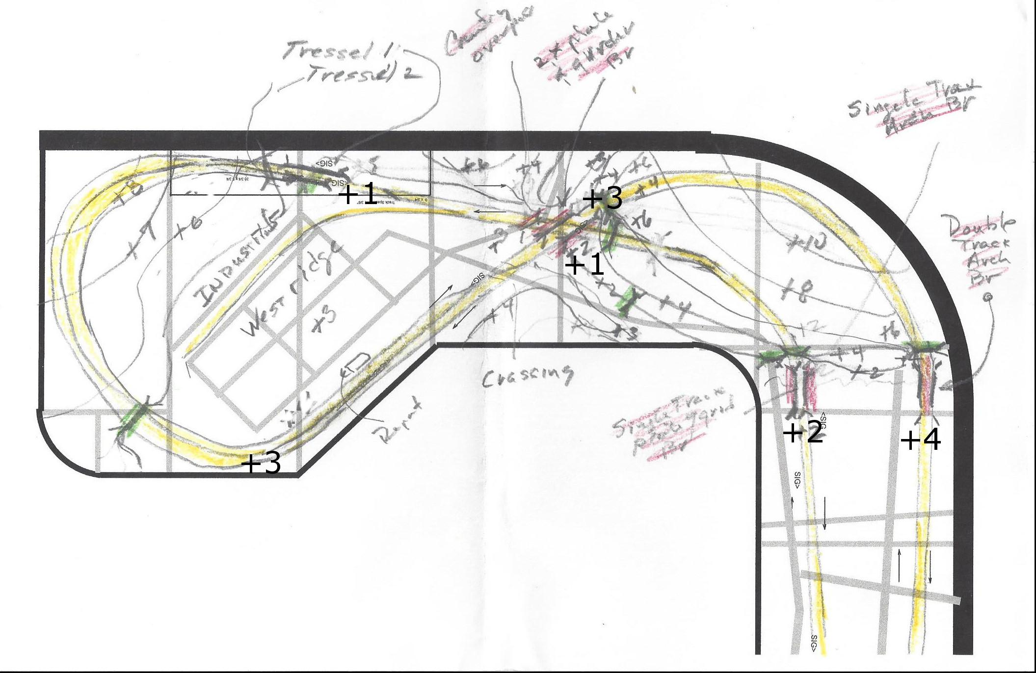 |
Here is the rough topo of Westridge and
the East River Curve with the track in yellow and the bridges in red
and the roads in gray. Notice the detailed elevation notes, not only
for
the roadbed, but also for the mountain terrain. This is a
crossover loop, with the track by the backdrop on the East bench
crossing the lake 4 inches above
the lake elevation of +0 and ramping down 1 inch around the curve and
tunnel and then continuing flat at +3 past the depot and
then ramping down again at 2% around the big curve in a tunnel down to
elevation +1 to cross back under itself and connect back up to the
East
river depot entrance at +2. As before these topo sketches are pretty
rough, and the terrain will undoubtedly change a
little as the installation progresses. Still, they supply a
good staring point for constructing roadbed runners and installing all
the bridges. |
Dismantling and Storing
Components from the A&BR1
11-29-2017
At this point I have removed almost all of the electronic components
from the A&BR1, so I might as well completely dismantle to old
layout and catalog all of the components for future use. I have
purchased some boxes for this purpose: 4"x4"x4" bakery boxes for the
small parts like figures, and vehicles and telephone poles etc. and
24"x24"x4" large flat boxes for structures, rock sections and trees
etc.
The first move will be to remove and store away the remaining
electrical components: namely the signal cards, ribbon cables and
masts, and the few remaining barrier blocks, and DS64s. Once that is
done I'll collect all the figures, vehicles, poles and other small
elements in the bakery boxes, and then put the structures in the large
flats. After that I'll get what I can on the trees and the rock
fragments. Finally, I pull up the track and the turnouts, which I hope
to resell. This is a huge job, and it will undoubtedly take months,
Once all of this is done, I'll hire a crew to remove the remaining
lighting, demolish and dispose of the bench work, knock out the walls,
and turn the room back into a garage bay.
Everything that is to be reused can be cataloged as it goes into the
boxes. Figures, vehicles, structures, trees, rock sections etc.
will
all have to be cleaned and touched up and refurbished. I'll probably do
this as I install these elements of the A&BR2.
December 2017
Building Roadbed Runners, Installing Bridges, and Laying Track on the
East River Curve
and at Westridge.
12/30/2017
I have been away for good part of December, but I have
managed to complete all the runners and install most of the bridges on
the East River Curve and on the crossover and loop at Westridge.
 |
Roadbed runners on the East River
Curve. Here the grade trasitions down from the higher roadbed along the
back wall at
East River down to the Westridge elevations for the crossover: +4 down
to +3 for
the high line and +2 down to +1 for the low line. |
 |
Roadbed runners and the Crossover at
Westridge. At Westridge the two mainline rights-of-way cross one
another while,and at the same time ,they cross the finger of a
small lake.
There are also two low tressels on the lowline that cross another
finger
of the lake and a marshy area. |
 |
Bridges for the Crossover at Westridge.
Getting all of this lined up was tricky. I used string for the fixed
and for the shifting radii and to define all the straight-aways.
Then I postioned the bridge abutments and installed the bridges to the
correct height, and finally, I built connecting raodbed to marry it all
together. |
 |
Thrre track-wide roadbed runners on the
Westridge Loop.
Here is the grade that transitions from high line elevation at the
Westridge depot of +3 down
to the low line elevation at at the crossover of +1. Most of this loop
will be hidden in a
mountain tunnel. |
The next move is to tweak
any offending track elevations in order to get all the grades nice and
smooth
and all of the places where roadbed sections join or marry to abutments
in perfect vertical alignment. Then I'll glue
down cork roadbed and lay and wire track. I then build the
backdrop silhouette around the East River Curve, and finally, I'll
rough in
the terracing for the town of Westridge and the topo forms for the
mountain, the lake shore, and the surrounding terrain. This will
take a few weeks.
At this
point I will not construct the two short sections of the back drop
silhouette: the one behind the long,
double-track bridge on the high line and the one behind the
low-lying
wetland on the low line. At this point I am not sure how I want to
handle the
silhouette behind these short sections. I think it will be best to
create the
silhouette in these spots as I create the terrain in front of it in
order to insure a good transition from the three dikensional scenery to
the two dimensional backdrop.
Also notice that, at
Westridge, the
track plan originally called for a siding, but given the
elevation changes and the way the terrain is shaping up, I have decided
to do away with it.
January 2018
Removable Hatch at Westridge
1-10-2018
Like the loop at Fitzhugh, the loop at Westridege is
hidden inside a tunnel. Regular semicircular loops look pretty
unrealistic on a model railroad, so I generally try to hide all or at
least part of them. This
can create track access problems, so I am always
careful to plan for good access. In the case of the A&BR2, both of
the mainline loops are in tunnels that can be accessed through
under-mountain cutouts in the backdrop wall. These cutouts allow
excellent access to the track in the tunnels, but in both cases there
are adjacent turnouts near the tunnel entrances that are difficult to
reach.
So, just as I did at Fitzhugh, I am constructing a removable hatch at
Westridge to allow good access to these turnouts should a problem
arise. I do not like to have to resort the removable hatches for track
access, but since I designed large radii loops for the turn-arounds at
the end of the line, I am forced to compromise here. I doubt seriously
if I'll ever use them, but should I have to replace a hard-to-reach
turnout down the road, I'll be able to get at it without too much
trouble. Murphy's Law states clearly that if a turn out is going to
fail, it will be the least accessible one. This is a codicil to the
part of that law that states that all derailments will happen inside
tunnels.
My hatchs are constructed of homasote, so they is light weight. Since
long expanses of homasote tend to warp easily, I have been careful to
add a
good number of supporting joists, also made of lightweight homasote.
At
Westridge, the hatch is just a flat surface, which will support the
street grid of the town. This means I'll have to glue the buildings at
Westridge down - something I generally do not do. I'll then bring the
mountain up from the west side of the hatch, and bring the slope down
to the wetland and lake on the east side. The south side marries to the
adjacent roadbed at elevation +3. Actually, the hatch elevation is 1/4
inch
higher order to accomplish a level transition between the thin platform
attached to the depot I plan to use here and the raised platforms that
will abut the
length of the siding. It is always nice to have structures complete and
on hand when
you plan and build the area that will support them. You can visualize
and measure all you want, but nothing beats seeing how a bridge, or a
platform, or a building will work in the three dimensional space it
will occupy as it
is constructed.
 |
The removable hatch at Westridge will
be the base for part of the street grid of the town. Notice that the
hatch
surface is 1/4 higher than the foreground roadbed in order to correct
for the height of the the depot platform vis a vis the raised platform
at track side. After adding the extra 1/4 inch, I use a .010 sheet
styrene plastic shim under the platform to get the elevation of
the joint exactly right. I'll make a low wall to cover the
mismatch at along the rest of the joint. It doesn't look like much now,
but this is
the kind of detailed planning
needed and the kind of extra detail required to make your scenery
interesting and special. |
Mainline Track at Westridge and the East
River Curve Complete.
1-12-2017
Today
I am declaring a
red
letter day on the AB&R2. I have completed the entire double
track mainline loop, and most of the associate backdrop
silhouettes all the way around the train room.
I began roadbed construction and track laying in May
2017. So it took about eight months to complete the loop's two
mainlines. I
thought
it might take as much as year.
Programming Schedules and Testing Track
1-12-2018
Now that the double track mainline loops are complete all the
way around the room, I can program some schedules and run a number of
different trains around the loops to test the track. I will begin with
four trains, 2 freight trains and 2 passenger trains, each programmed
to
make a complete loop, 2 trains in each direction. As I place each train
in service, I carefully clean and re-profile the associated
locomotives, make couple adjustments as needed, and replace the wheel
sets on all of the cars. Most of my
cars are long-overdue for wheel replacement, so this had to be done
anyway. This will ensure that I begin my testing with all the rolling
stock in tiptop shape and in precise adjustment. I will then test all
the trains, one at a time, around the entire layout. Any cars that show
repeated derailing problems will be removed and set aside for
adjustment or truck
replacement, and any bad spots in the track will be noted and repaired.
I can also check the accuracy of the 4D Sound location settings for
each block.
I began with the two freight trains, one in each direction, and found
they preformed pretty well. I did find 3 questionable box cars that
seemed to want to derail in several spots and a couple of couplers that
needed replacement. As for the track, it too was pretty good, although,
not surprisingly,
it needed a thorough cleaning to many places. I worked with my bright
boy track cleaner and some alcohol, I noted a few bumps that need
leveling out, and I fixed a few rail joiners the were not perfectly
married, removed a hold-down nail or two that I had missed, and made a
few track alignment adjustments. Within a day, I had both freight
trains
running reliably around the layout. I next did the same for the two
passenger trains. Once they were running smoothly and without
incident, I sequenced multiple schedules to run all four trains at
once, staggering their starts and stops to create a sequence that moves
all four trains around the two loops with station stops, light and
engine sound on/off commands, and arrival, departure, and warning
horns at all the appropriate spots. I also set some speed limits and
markers in the mainline block adjacent to all of the depots, so any
passing trains will slow to 40 mph as they pass each depot.
Now, I can run this
master
sequence a few times each week to keep things in adjustment and to
help keep the track clean. During these runs, I'll keep careful
notes of all derailments and coupler problems in order to identify any
track areas or cars that exhibit recurrent problems. At some point down
the road, I'll add two more passenger trains schedules to this master
sequence. This will complete the mainline schedule programming for my
demonstration sequence, and to complete the presentation, I'll have
only to add a few, short switcher schedules
to create activity in the yard, the turntable, and the terminal
area.
|
The two freight trains at the Westridge
cross-over. |
Installing
a Faller
Double Track Arched Steel Bridge
1/17/2018
Getting back to the layout construction, the next order of business
will be to install the remaining bridge, near the newly completed East
River Curve.
At the far left (north), on the double track high line, on the east
bench above the town of East River I
plan to have a long Faller Steel Arched Bridge cross the finger a small
lake.
I have taken to modeling the fingers of lakes instead of rivers on the
A&BR2. The advantage is that they don't have to completely cross
the layout
and therefore unrealistically terminate into the edge of the
bench. In the
Smokey Mountains TVA lakes with their narrow fingers snake about
seemingly
everywhere, and the surrounding terrain is often quite rough, so my
many lake crossings on the
A&BR2 are indeed prototypical.
I have said several times in this blog that bridges are all best
installed at
the time of track laying. It is much easier to get the abutments and
piers just
right and to get everything sturdy, square, level, and in perfect
alignment
when working with a homasote base and a cut-lumber or homasote frame
attached to the
roadbed ends. The rocky terrain scenery can then easily be built to
cover any
wooden framing needed.
Below is a photo of the roadbed installation with the elevations for
each end
of the bridge set exactly. A homasote base will act as the lake
surface
and will also support a wooden frame to which I will attach the stone
abutments
at either end of the bridge and the footings for both ends of the steel
arch
below.

|
According
to the graphic on the Faller model's package, the bridge is 954 mm long
and 131 mm high, or 23.386 inches long and 5.157 inches high. I have
made my opening in the roadbed about 26 inches wide and installed the
top pf my
homasote
base 5.5 inches below the lower of the two roadbed ends (this bridge is
on a grade and the northern end will be about 1/4 inch higher than the
southern end). So I have left myself about
three inches of play in width and more
or less 1/2 inch of play to shim and make perfecting adjustments in
height. Once the bridge is in place, I can fill the remaining
gap in the road bed, and the scenery will cover
all the supporting structure including any shims. My lake will be
shaded to create the illusion of depth terminating into a distant
shoreline mountain on the backdrop wall with rows of even more distant
mountains visible beyond that. Notice that the roadbed is not set all
the way up against the wall. This allows me to bring the sceney down from the roadbed to the lake shore
in a way that will suggest that there is much wider expanse of water
behind the abutments and that this narrow finger opens into a much
wider and expansive lake behind the bridge. |
The
next move is to build the bridge.
 |
Here is the completed bridge on the
bench top with some temporary blocking to keep it from sagging. I have
painted the bridge black, the concrete footings light gray, and the
stone arched abutments dark gray. I will come back and weather the
bridge using a little rust all, and I'll weather-dry-brush lighter gray
highlights into stone work later when I begin the surrounding scenery. |
Next I cut four supports: two to support the ends of the arched
abutments and two to support the concrete footings for the steel arch.
I will
also put shims under the long ends of the of the stone arched abutments
so they are firmly supported. Once all of this blocking is shimmed to
exact height and glued in place with the bridge abutments and footings
glued to it, the structure is perfectly level and
quite sturdy. The track can then be glued down to the bridge decking,
and a short piece of homasote roadbed can be fitted to support the
track at the left end of the bridge. Making the opening just a little
too wide and a little too high made setting the bridge in place and
making adjustments easy. Once everything is set, it is also easy to
fill the remaining short gap.
 |
I have cut away a little more of
of the homasote in the foreground to open up the gorge a little more,
so I can have a less steep slope down to the lake. I'll hold off on
installing the backdrop silhouettes behind this scene until I have
experimented a little with making the transition from the 3 dimensional
model to the flat 2 dimensional backdrop. Creating the model lake
surface will be straightforward enough, as will painting the lake on
the backdrop - but getting the two to seamlessly marry might prove
tricky. So I'll build a little test diorama to experiment on. |
Constructing the Rough Mountain Frame
on the East
River Curve
1-23-2018
As always, I begin with homasote supports for the tunnel
portals.
This helps to define the mountain space and positioning. In this case,
both main line track pairs will pass through the tunnel, so I have four
double track portals installed. These are a bit wider than the
plaster
castings I made to attach to these supports, but it is not a problem to
cut them in two, glue the two half to the portal, and then fill in
the gap in the middle of the top
of the portal with homasote and fashion it to match the stone work. A
road also
passes through a tunnel in this mountain (the main high way from East
River to Westridge), so I'll have to install the roadbed and add two
more smaller portals supports.
Once the six portal supports are in place, I'll place a large sheet of
homasote flat against the curved corner radius backdrop wall and draw
the contour of my mountain on it. Then, following my line, I'll cut out
a 3 inch wide mountain cross section and screw it to the curved wall.
Next, I'll fashion two more mountain cross sections, each lower than
the last, and attach them to the bench parallel to the tangent at the
center of the curved corner wall: one about in the middle of the bench,
and
one about a foot from the edge of the bench at the corner. Finally,
I'll fashion a few cross braces and screw them in place using sheet
rock nails. The whole thing should truss up at this point and become
quite rigid. I
will come
back later and add more bracing to support my plastic screen cover when
I am ready to proceed with the landscaping in this area.
 |
The rough mountain framework covering
the EastRiver Curve:view from the north. Notice the cutaway section of
the backdrop wall supplying access to track under the mountain. |
 |
The rough mountain framework covering
the East River Curve: view from the west. I'll add more cross members
at a later time.
|
I have a have a sturdy basic framework completed, which defines the
postioning and the look of the finished mountain. Finally I have
cut away the sheet rock in the underneath section of the backdrop wall
from the sheet rock overhang I designed earlier. This will allow
ample access for cleaning and maintaining all the track in the
tunnel.
Constructing the Rough
Mountain Frame at Westridge
1-23-2017
Another large mountain will cover the entire turnaround loop at
Westridge. The method here is the same as with the mountain above:
tunnel portal supports, wall silhouette, additional cross silhouettes,
some cross bracing, and the sheet rock cut-away. The sheet rock
cut-away will give good assess to most of the track in this large
tunnel, but I will have to install a removable section of scenery over
the low part of the mountain frame near the front of the bench in
order to get to that section of the curved track in the tunnel. I'll
inthe next day or so.

|
The rouhged-in mountain frame at
Westridge with the roughed-in mountain frame on the East River Curve in
the the back ground. |
In the meantime, I have been running my test schedules, and making
adjustemnts to track and rolling stock, as well as programming and
adjusting lights, sounds, and stop and brake markers in
TrainController. At this point things are beginning to
run smoothly.
So the initial phase of work on the A&BR2 is almost complete. I
have only to finish
gluing down ties to fill the joiner gaps in the newly laid track at
East River and Westridge. This will only take a day or so. Then I'll
build
the additonal hatch in the new mountain form and complete the
salvage operations on
the old trainroom. Finally, I'll install all the signals and the
Digitrax signal card and program the signal matrix in TC. This will
take several weeks or more.
Salvaging Components from the A&BR1
1- 26-2018
This is a big job, but I have been working at it on and off for the
last month or so. The large, flat boxes I bough are perfect for the
temporary storage of structures, and the small bakers boxes are working
well as a temporary home for small details, like figures and vehicles
and fenses etc. To date, I have salvaged all of the electronic
components except the signal system and about 80% of the structures,
trees, rock faces, rock walls, and detail scenery as well as most of
salvageable wire. It should only take me a few days finish. I'll then
hire a crew to tear out the bunch work and trun this back inot a
garage.

Before |

After - very sad! |
Before I can reuse any of the old scenry components from the A&BR1,
I'll have to reburbish each piece - cleaning and touching all up the
structures, re-folaiging and touch-up painting all the trees,
cleaning and repaintng all the rock and wall forms, cleaning and
re-touching all the figures, vehicles, and other detail elements, etc.
I'll probably do this in small batches as I place these components back
in
service on the A&BR2.
Installing Mainline Signals on the
A&BR2
1-27-2018
Way back when I built the prefabricated turnout modules, I worked
out the locations of all the mainline signal and drilled most of the
holes for their installation. So part of the signal installation
process is already complete. My blog entry from 7-4-2006 dicusses this
process and details the protpcol I use for programming signal triggers.
I have now only to install the Digitrax
Se8c Signal Controller Cards, run the ribbon cables, and install the
masts in my pre-drilled holes. Each card has eight output pinsets for
1p in ribbon cables, and
each pin set will drive two double headed signal masts. The 64
addresses
for the sixteen masts are preset depending on the board number
assigned to the card.
I'll begin using the salvaged cards, ribbon cables, and signal masts
from the
A&BR1. Most of these masts already have their double headed heads
detailed with targets. I will paint each mast and
install targets on all signal masts before
installation. There will be more detaiing to come (electrical boxes,
ladders, and service platforms, signs etc.) but these details will come
later. For now, I'll not fill the holes so I can remove these
masts when I get around to this further detailing.
The first order of business is to work out the best location for the
Se8c cards in order to minimize cable lengths. I have two of these
cards, and each card can drive up to 32 heads (16 double headed masts)
using 8 ribbon cables. I plan 34 mainline signals mast, so I'll have to
order a thrid card. I have decided to use board addresses 8
(addresses
706-768),9 (addresses 769-832), and 10 ) addresses 833-97 in order to
keep the signal
addresses from overlapping with any of my DS64 turnout address which
are in sequences beginning with, 100, 200, 300, 400, 500, and
600. I'll mount one card on the wire mounting board on the
Fitzhugh side of the north bench to power signals at Fitzhugh,
Altamont City, and the
entrance to Altamont Termnal, and one card near the center of the south
bench to power
masts at Altamont Yard and Little River. I
plan to run the
ribbon cables loosely along the back of the mounting board. I'll assign
each set of addresses for
each mast in TrainController and test each mast as I install it.
Each signal head on each mast gets two address and I have
named each head to reflect its position on the Se8c card and its
address. For eample, the top head on the first signal mast I installed
is called "8-1A Top 705-6" - that is, card #8, Output #1, Orientation
A, top head, using addresses 705 and 706. Once all of this is done, I
can later go back into TC and
program the locic for each head - a long and arduious process.
 |
SE8c installed on the wire mounting board |
 |
Mainline Signals with targets only in
place at Fitzhugh. |
2/4/2018 Progress Report:
I have completed the installation of the
first two Se8c cards and all the mainline signals at Fitzhugh, Altamont
City, Altamont Yard, LittleRiver, and the South entrance to the
depot sidings at East River - 14 ribbon cables in all - that is, 28
double headed masts. The 15th and 16th cables will go to the four
signals I plan to install at the entrances to the Altamont Terminal
section on the center bench section, when I get around to building
that. I plan to fully complete the periferal bench scenery before I
begin track laying on the center section, so it will be a long while
before start on the center bench.
All 28 of the installed
siganl masts have their addresses entered in TrainController, and I
have completed the trigger programming for the 12 signals at Fitzhugh.
I
have ordered a third Se8c card and a few more masts to complete the
installation at East River and West Ridge.
While I am waiting for the new card to arrive, I have been continuing
to run my test schedule routines and to tweak track, couplers, trucks,
and wheel sets. At this point, all mainlines are running almost
perfectly including the master narration, station announcements, and
room light programmng
for both HUE lights and flourescents to create sunrise and sunset
effect. I have made a few temporary adjustment to track and turnouts in
a few spots, and at some point I need to go back and glue
these adjusted sections of track down. I have also finished
replacing the wheel sets on all my passenger and freight cars.
In addition, I have been doing a careful, systematic track cleaning of
all mainline track all the way around the layout. I do this a little at
a time in small sections, and I should be finished by the middle of
this week
when the new signal card is due to arrive. Finally, tomorrow I will
build and paint 25 more drawf signal boxes and install them on the
remaining uncovered LEDS on the mainline, and I'll finish glueing the
targets on all installed mainline signals.
Further Progress Report 2/12/2018:
The new Se8c cards arrived along with a few more signal masts, and I
have installed and tested these at Westridge. Today I'll enter the
addresses for these signals. I have ordered more 3 aspect targets
from Shapeways, the 3D printing company, and when these are installed,
I will have completed the mainline signal installation, except for
programmng all the triggers. So far I have programmed triggers for 20
of the 36 installed mainline signals. I have also pretty much finished
the track tweaking and re-glueing. All my test schedules are running
smoothly, but for a few pesky coupler issues. The thorough track
cleaning is almost complete.
Mainline Track, Signals and Topo
Rough-ins Completed
2-15-2018
I finished programming the mianline signals triggers today, so I am
going to call the second phase of this project complete. The first
phase was to construct the train room, to install the lighting and
sound systems, and to construct the
bench work. The now-completed second phase was to construct the
outer-loop roadbed and to lay and wire track and signals for all
the mainline track, as well as to construct complete backdrop
silhouettes and topo rough-in-framing and terracing all around.
Except for installing
the signal targets on the last six signals and fabricating a few
backdrop silhouettes in areas where I am still trying to figure out
what I want to do, I am now finished. Of course,
running comprehensive test schedules and tweaking track and
couplers will continue for months. Below is a set of photos
detailing the entire finshed second phase.

North Bench - Westridge looking East |

North Bench - Westridge looking West |

North Bench meets East Bench - East River Curve |

East Bench - East River looking North |

East Bench - East River looking South |

East Bench meets South Bench - Little River Curve
|

South Bench looking West from Little River
|

South Bench looking East - Altamont Yard |

South Bench meets West Bench - Altamont Curve |

West Bench looking South - Altamont City |

West Bench looking North - Altamont City |

West Bench meets North Bench - Fitzhugh Cirve |

North Bench looking East - Fitzhugh |
 North
Bench looking West - Fitzhugh North
Bench looking West - Fitzhugh |

The center section will serve as a large work bench until the periferal
scenery is complete. |
Salvage Operations on the A&BR1
Complete
2-16-2018
Today I completed salvage operations on the A&BR1. All the
structures, vehicles, figures, and other details are boxed up along
with the remaining
electrical components, and a
large asortment of trees, clump foliage, and foam rock pieces, which I
have boxed up for reuse after refurbishing. I have moved all these
boxes to the new train room and stored them under the center section
bench which currently serves as a large work bench. This Spring I'll
get a crew up here to demolish the bench and walls and return the space
to it's former function as a garage bay.
 |
Temporary Storage Boxes for A&BR1
structures and other salavged scenic details now stacked under the
center bench in the new train room. |
Planning a Scenery Section 2-18-2018
I like to build scenery section by section, working on small
managable areas from back to front. I generally begin a section at the
backdrop wall and work toward the aisle-side bench edge. This way I can
get a consitant look front to back. In the cases where false
perspective will come into play, I often work both forward and backward
from the place where the forshortening begins. As I go a try to keep in
mind the plan for the adjoining sections so I can accomplish a smooth
transition. Before I being each section I sketch out a rough plan.
I have decided to begin building scenery on the mountain that covers
the East River Curve in
the northeast corner of the train room.
This mountain is flanked by two lakes, so on boths sides there is a
steep fall from mountainside down to the lake bed. I'll have to be
careful with these transitions.
 |
I'll begin building the scenery here. |
First I'll sketch a plan. In this section, like most sections, I
already
have a pretty good idea
of what I want to do, so the plan will merely detail
the locations of things in overview. Where will the
foreshortinging begin? Where will there be structures, fileds, trees,
rock faces, embankments
etc.? I have found that a good and easy way to sketch such a plan is to
simply draw it in on a photo of the rough-in like the one above.
 |
Just a rough idea so I can place the
teraces for structures and the larger rock formations onto the frame
work before I begin to install the plastic screen. Notice I have
indicated the positioning for rock face, meadows, forests, as well as a
rough idea of the forced perspective filed at the top. All of this can
be
adjusted as the installation proceeds, but for now, this give me a good
place to start. |
Ongoing Tweaks to Track, Wheels,
Trucks, and Locos 2-19-2018
This is really tedious work. I have my track pretty well
adjusted by now, and I am experiencing no significant derailments owing
to uneven trackwork. There are however, a few waggles or dips that
I have noted, which need to be straightened out or adjusted sometime in
the future. Likewise, all five of my test trains seem to me preforming
well, with two exceptions.
First, three of my older locomotives are experiecing occasional stalls
upon the
application of restart voltage after a stop. I have cleaned everything
I can (track, wheels, cups, wipers etc.) to no avail. If I run one of
these locos without the shell and stop and start it unitl it stall, I
can very carfully check continuity between the track and wipers and
the farme. It appears that the failure is either with the wipers or the
axel cups. I have order new trucks.
Second, two ConCor passenger cars, a baggage car and a trailing
observation car will not stay on the track. I have noticed that the
MicroTrains trucks that came on these cars are different from the model
1017 and 1018 trucks that I use elsewhere and I like so much, so I have
ordered 1017 silver trucks for all six cars.
Other than that all the test schedules are running pretty
well.
2-28-2018 Progress Report: The new truck did the trick on the Con-Cor
silver cars and the entire train is now running reliably. As for the
stalling issue swith the older locos - I am stumped. The new truck did
no good at all, and I now suspect the motor, because further testing
between the frame and the track seems to indicate some kind of
semi-short on one side. The continuity is there, but the voltage is
seriously reduced just belfore the stall. Curious?
Notes Regarding Latex Wall Paint
2-20-2018
Back in May of 2016 I posted a discussion of spray paint and acrylic
brush-on pints for modeling. (See entry of 5-10-2016) To complete my
thoughts on paint, here is a discussion of the third major painting
component: flat latex wall paint.
On my model Railroads regular old falt latex wall paint is a real
workhorse. I use it for painting the backdrop wall and also as a
base
coat to color and seal all
foam and sculptamorld surfaces, be they rocks, meadows, forest floors,
lawns or
whatever. With all of theseuses, a number of colors
are involved. I used to mix my own colors in batches using white, black
along with a basic brown and a basic green. This worked pretty well,
but even
with the most precise measuring, these hand mixed colores were nearly
impossible to exactly match when a second batch was required. Then I
discovered that Benjamin Moore professional paint stores,
offer 1 pint cans of custom mixed falt latex paint to match any color
in their vast
collection of colors. They are perhaps a little pricey at about $7 a
pop, but remember on a model railroad 1 pint (16 oz.) is a hell of a
lot of paint. (I have since found that Walmart offers the same thing
for les than 1/2 the price.)
These sample cans have several advantages. First, they can be matched
almost exactly if refills are needed, and thus the entire layout gets a
more uniform look. Second, and perhaps more importantly, they offer a
range of colors that allows the modeler to really refine his or her
color schemes. For example, before I started using these sample colors,
I was mixing my grays for rock outcroppings and my stone walls using
grays created from various combinations of black and white: usually
three shades - a dark coat first for under-coat, a medium gray light
over-brushed for the basic rock color (applied lightly enough to allow
the
creveaces to remain dark), and finally a very light gray or white,
dry-brunshed on to add highlights. This worked pretty well, but I now
find that using the store-bought mixed colors, I can get a little dark
green and brown in the gray under-coat and a little earth tone in basic
rock color.
This is subtile, but it definately makes a difference. There is more
interest, more
softness, and more depth with these custom colors. I used to do a
little tinting in my hand mixed colors, but getting the exact right
shade was difficult. With the sample cans from the paint store, I can
select my colors from the color charts and get exactly what I
want every time.
In addition to the three grays, I use two dark green colors for lake
surfaces (darkish for deep water and a slightly lighter and more
brownish shade for
shallow areas). I also use three greens (dark, medium, and
light) diluted
for refurbishing clump foliage and trees salvaged for the A&BR1. I
also keep on hand larger cans of the backdrop skycolor and a red-brown
earth color that I use as an undercoat for all ground areas, be they
fields, forest, enbankmenst or whatever, and adarker brown to
over-brush (while still wet) the redbrown for forest-floor areas.
One final note on using latex wall paint. If you are planning to do as
I do and dry-brush one color over another in order to create depth, it
is a
must that the first
color be fully dry and set
before the next coat is
applied. Even though this kind of paint appears to dry quickly,
it generally takes several days for it to fully
set. Otherwise, the second coat disolves the first, and you get a
muddy mess.
Scenery Building Begins at the
Mountain on the East River Curve
2-21-2018
I begin by adding two small terraces and a lot more cross bracing to
the roughed-in frame. The falt terrances will be the lots for two
Victorian mansions high on the mountain (one N scale and one farther
back
in Z scale), and the extra cross bracing will support the plastic
screen covering. In the steep spots these braces will supply places to
nail down the rock
faces that I will install in the next step.
Here is the rouughed-in frame before I began. |

Here is the frame with more bracing and the two terraces. |

Here rock faces, portal masonry, and stone walls have been
added. These rock faces and outcropings are already painted because
these pieces were salvaged from the A&BR1. I'll repaint them when I
paint the sculptamold. |

Screen intalled.
|
Most of the rock faces, walls, and outcroppings I create are made
from a ridgid foam product from ISLE. This stuff is sold as single
large 3 dimensional piece called a "Multi-Scale Embankment" and it is
easy to cut it up into whatever shapes and sizes you need. The initail
insatllation of these pieces do not require precision, beause it
is quite
easy fill the gaps and to tie all the pieces together using
sculptamold,
which can be shaped, moulded, carved or even sanded to match the look
of the
rock foam. Here I have used sheet rock screws to attach most of the
pieces. I do occasionally use glue (Liquid Nails), and I also use
this heavy glue to attach the plaster-cast portals to the homosote
frames I
installed earlier. However you attach these features does not really
much matter, because once the sculptamold sets up, the entire mountain
will become one rigid, strudy, hard, light-weight piece.
At first blush it would appear best to apply the sculptamold beginning
in the back next to the backdrop wall and to work forward toward
the
bench edge. However, I began with the sculptamold around the
portals and exposed rock faces. This is the more tedious and exacting
part of the work, it takes longer, and most importantly, it requires a
much thicker
more moldable sculptamold mix than needed when just spreading
it on an open space. This thicker mix should be thick enough to
hold together in large gobs, but still thin enough to shape smoothly
with
a palate knife. As it begins to set, it can be carved more accurately,
so I work in small areas, mixing small batches of sculptamold as it
tends to start setting up after 10 or fifiteen minutes. The work done
in the first picture
below was done in three batches of about 1 to 1 1/2 cups of mixed
sculptamold goo. The flat areas will go muh faster. It took me
about an hour and half. The next two
pictures show details of how the rigid foam rock pieces are tied into
the
mountain and tied together, and how I use this gobby mix to filled
the gaps between the foam rock and the portal halfs, and to fashion
adjoinng rock formations, embankments, and other terrain features. This
looks pretty sloppy in the photos at this early stage, but it is not.
The sloppy look comes from the color contrast. If you look closely, you
will see there is considerable detail sculped into the sculptamold
connecting rocks. When painted and detailed with groundcover, foliage,
and trees, my
sculptamold rocks will be indistinguishable from the rigid foam rocks
they adjoin, and the over-all effect should be pretty convincing.
|
Lower portion around the tunnel portals done using three small batches
of thick sculptamold. The sence of forced perspective and the illusion
of increased depth is already evident. |

Here is a close-up showing sculptamold adjoining rocks, platercast
stonework, and
tie-in detail. Of course, I had the track covered with a drop-cloth
while I did
this. Looking at this, I think I'll go back and change the look of the
rock face between the portals to something with more mass and depth,
and I'll also add another retainlng wall on the left of the samll
roadway portal. Also when this dries a little, I'll be able to better
articulate the stone work in the patch in the center of the large
portal. |
It took a little over a week, working a few hours each day, to
complete the additional bracing, cover the entire thing with screen,
and then add the sculptamold. Once
the
sculptamold was completely dry, I applied the first coat of paint: a
dark gray undercaot for all rock faces and stonework, a red earth
color undercoat for meadows, fields and other open areas, and a darker
brown undercoat for forest floors, thinkets, and wooded areas. One
does not have to be too careful here as almost all of this piant will
eventually be covered up. I just pour out the paint I'll need into a
small cup, thin it just bit with a little water so it will flow into
all the cracks, and lay it on thick to ensure complete coverage. Where
the differnet colors intersect, I go back with a small brush while it
is still wet and blend the to two colors just to soften up any hard
edges or lines. After it is comletely dry, I go back and retouch the
tiny white spots that may have appeared.These always tend to appear as
the
drying paint shrinks.

Here is the entire mountain with the sculptamod appled. |

Painting: a dark gray undercaot for all rock faces and stonework, a red
earth color undercoat for meadows, fields and other open
areas, and a darker brown undercoat for forest floors and wooded areas. |
The next step is to finish coloring the exposed rock faces and
stonework. This requires two layers of dry brushing, a technique
critical to this kind of modeling. It is very important to let the
first latex coats dry completely before attempting to dry bruch over
the dark gary rocks. Otherwise the second color disolves the first
color and your get a muddy mess. Even then, when dry brushing latex
wall paint over latex wall paint, one must go at it lightly and avoid
too much scrubbing. First, I dry brush a lighter gray applying enough
color to cover much of the exposed rock faces but allowing all the
cracks, seams,
and indentations to remian dark. When this is completely dry, I use a
very dry brush and white latex paint to add highlights. This takes a
little practice, but it is not a dificult technique to master. Dip a
old 1 inch wide brush in thick flat white latex wall paint, rub the
excess off the bristles on the lip of the paint can, wipe the bristles
with a clean rag, and then work out almost all of remaining the paint
by rigorously and forcefully painting swirls on clean dry newspaper.
Use several sheets, and work it until it is pretty dry and almost no
paint is left in the bristles. Now just touch it to the rock face using
very light strokes that touch only the highest projections of rock. Go
lightly at first and harder as the brush become dryer and dryer. You
should be able to create a feathery highlighting that makes your rocks
eally
come alive. Practice a little, and you will get the hang of it.
 |
Here's the finished paint job and
highlighting for the rock faces. I'll go back when I do the foliage on
the rocks and use
some
colored washes and chalk pastels to color in moss, dirt, leichen, etc. |
Now that the intial dry brush rock hightlighting is complete, I am
ready for the ground cover; but first, I'll tend to the backdrop
silhouettes on the adjoining sections so that, as I
progress with the mountain, I can make believable transitions from
distant mountainside to backdrop scenery.
This blog has gotten so long that it may take too long to load on some
compluters. Accoringly, I'm starting a second page.
Go to Page 2 (3-2018)